
Detector element matrix for an optical position measuring device

A technology for detecting components and measuring devices, applied in measuring devices, converting sensor output, instruments, etc., can solve problems such as low pixel density, achieve high pixel density, good signal quality, and reduce connection costs

Inactive Publication Date: 2010-09-08
DR JOHANNES HEIDENHAIN GMBH
View PDF3 Cites 0 Cited by
  • Summary
  • Abstract
  • Description
  • Claims
  • Application Information

AI Technical Summary

Problems solved by technology

The number of detection elements available per unit area is also reduced due to the laborious connection, i.e. resulting in a relatively low pixel density

Method used


Image

  • Detector element matrix for an optical position measuring device
  • Detector element matrix for an optical position measuring device
  • Detector element matrix for an optical position measuring device

Examples


Embodiment Construction

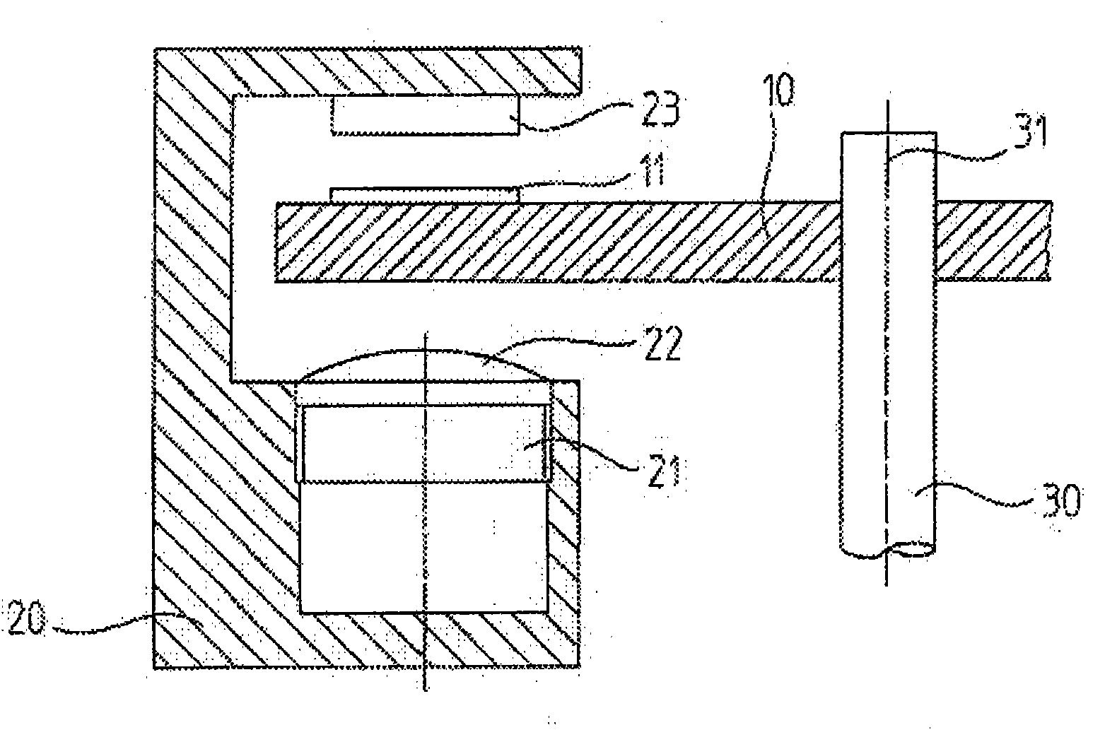
[0044] exist figure 1In a very simplified illustration, a rotating optical position measuring device is shown, which is formed by an array 23 of detection elements according to the invention. The position-measuring device is used to generate position information and the relative movement of a body rotating about an axis 31 , which is not shown in the drawing. Such a position-measuring device can be used, for example, in machine tools or electric drives and there provide a superordinated control unit with information about the position of the rotating body.

[0045] Such a position-measuring device comprises, on the one hand, a scale 10 on which an incremental measuring scale 11 is arranged. The measuring scale 11 consists of a track arranged circularly around the axis 31 and has selectable transparent or opaque scale areas, which are each rectangular, the opaque scale areas can be provided with a chrome layer, for example. The dial 10 is arranged centrally on a shaft 30 rota...


PUM


Abstract

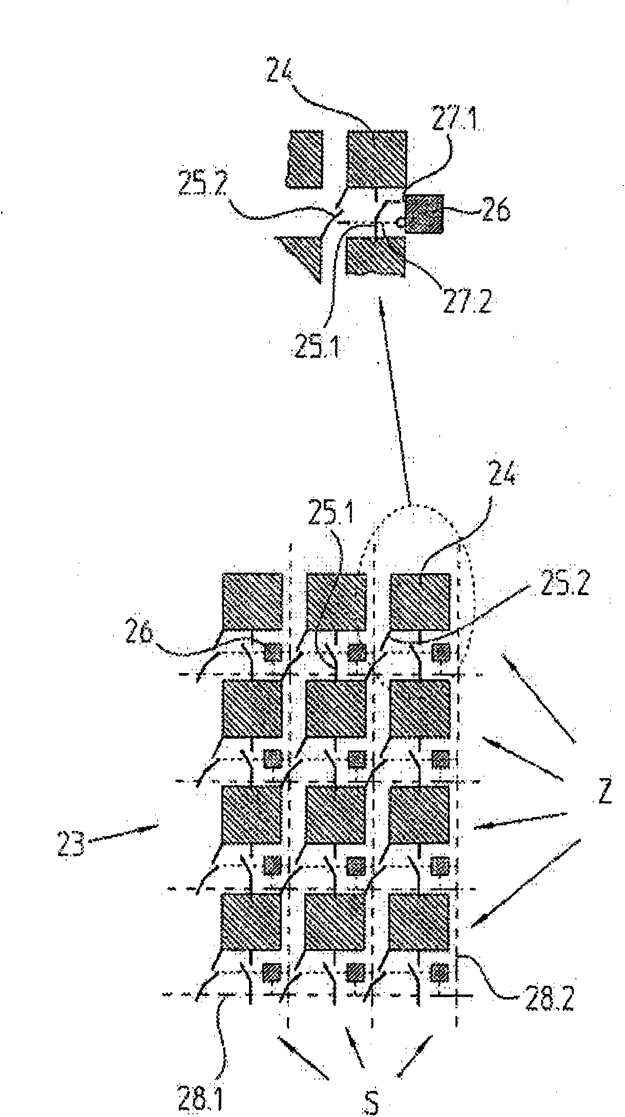
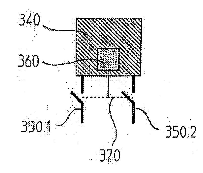
The present invention relates to a detector element array for an optical position measuring device, which array can be used to convert a strip pattern resulting in a detection plane into electrical scanning signals. The detector element array comprises a plurality of light-sensitive detector elements which are arranged in rows and columns in the form of a matrix. At least some of the detector elements are assigned no more than two switches which can be used to optionally connect each detector element to adjacent detector elements directly. At least some of the detector elements are assigned a memory element which can store information which indicates the adjacent detector elements to which a particular detector element is connected via the two switches in a scanning configuration which has been set. The two switches can be used to optionally establish a direct connection to an adjacent detector element in the same column and / or a direct connection to a diagonally adjacent detector element in an adjacent column of an adjacent row.

Description

technical field [0001] The invention relates to an array of detecting elements for an optical position measuring device. Background technique [0002] Known optical position measuring devices generally comprise a measuring tool and a scanning unit which is moved in the measuring direction for this purpose. The scanning unit and the measuring tool are connected via two objects whose relative and / or absolute position relative to one another is to be determined. In the case of length measurement, the measuring tool is formed as a linear measuring ruler with a measuring scale extending in the measuring direction, and in the case of rotary measurement as a graduation plate with a circular measuring scale. In addition to one or more light sources and optical elements such as lenses, scanning gratings, etc., the scanning unit usually also includes detection means. In the case of an incremental position measuring device, the detection device scans a periodic fringe pattern in the ...

Claims


Application Information

Patent Timeline
Patent Type & Authority Applications(China)
IPC IPC(8): G01D5/347
CPCG01D5/34715
Inventor J·奥伯豪泽
Owner DR JOHANNES HEIDENHAIN GMBH
Learn More