
Multiple antenna loop configuration for electromagnetic inducing system

An antenna and loop technology, which is applied in the field of multiple antenna loop layouts, can solve problems such as the difficulty of making panels with small border areas

Inactive Publication Date: 2003-08-20
WALTOP INT
View PDF0 Cites 3 Cited by
  • Summary
  • Abstract
  • Description
  • Claims
  • Application Information

AI Technical Summary

Problems solved by technology

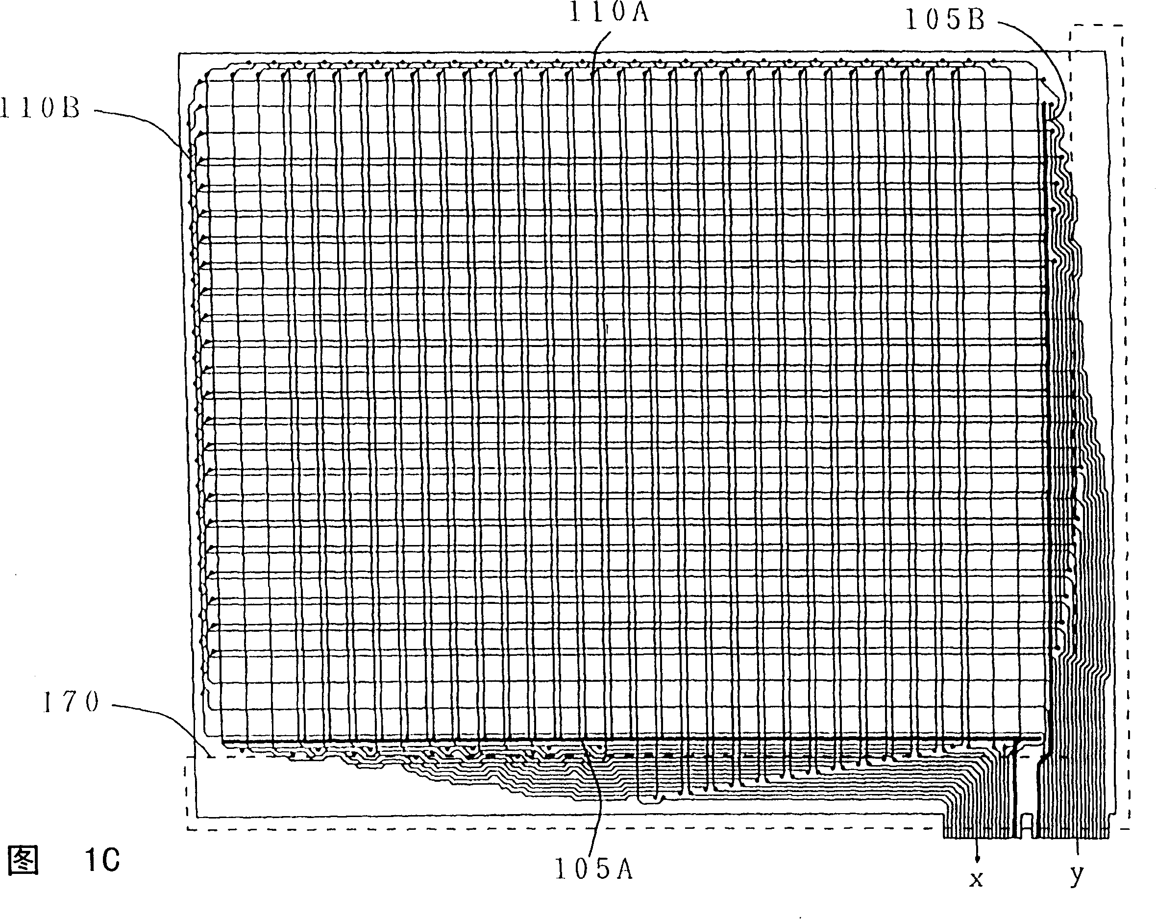
Therefore, the traditional digital board must reserve a boundary area 170 to place part of the antenna loops 110A and 110B that exceed the ground wires 105A and 105B, which limits the size of the tablet and makes it difficult to manufacture a panel with a small boundary area.

Method used


Image

  • Multiple antenna loop configuration for electromagnetic inducing system
  • Multiple antenna loop configuration for electromagnetic inducing system
  • Multiple antenna loop configuration for electromagnetic inducing system

Examples


Embodiment Construction

[0023] The direction discussed in the present invention is a multi-antenna loop layout of an electromagnetic induction system. In order to provide a thorough understanding of the present invention, detailed process steps or structural elements are set forth in the following description. Obviously, the practice of the invention is not limited to specific details familiar to those skilled in the art of circuitry. On the other hand, well-known elements have not been described in detail in order not to unnecessarily limit the invention. Preferred embodiments of the present invention are described in detail as follows, but in addition to these detailed descriptions, the present invention can also be widely implemented in other embodiments, and the scope of the present invention is not limited, but the patents defined by the claims The scope of protection prevails.

[0024] Referring to FIG. 2A, in one embodiment of the present invention, a multiple antenna loop 200 is first provi...


PUM


Abstract

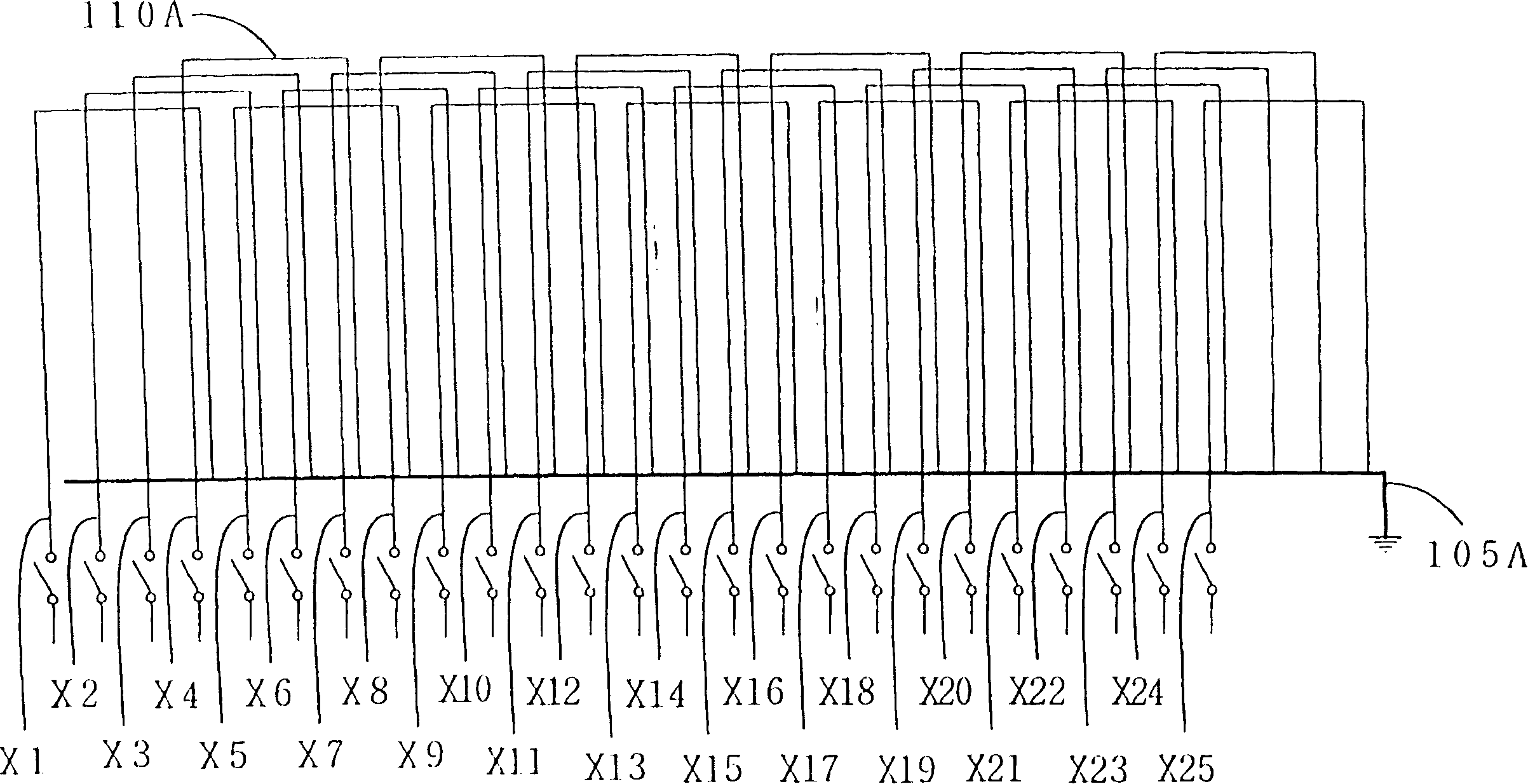
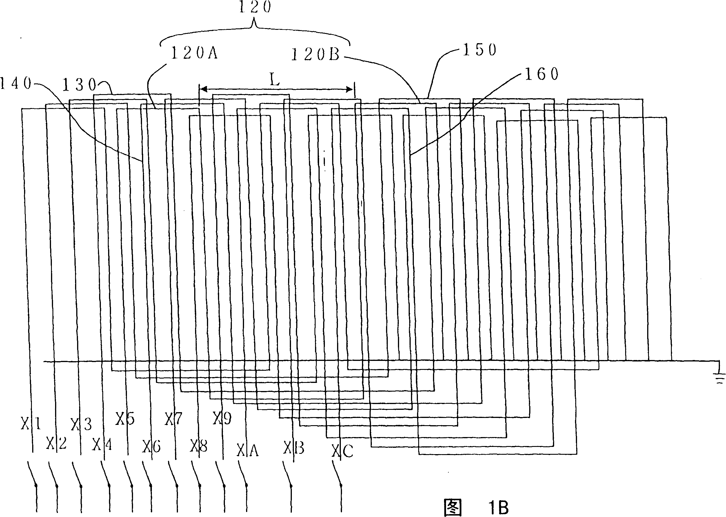
The multiple antenna loop configuration for electromagnetic inducing system includes several antenna loops and each of the antenna loop has one end contained to an antenna switch and the other end connected to earthing wire. Each of the symmetrical antenna loops has several n-shaped sections to form sawtooth area and constitute several quasi-closed areas. When the symmetrical antenna loops are inphase, the n-shaped sections form the sawtooth area in non-cross mode; and when the symmetrical antenna loops are in phase opposition, the n-shaped sections form the sawtooth area in cross mode.

Description

(1) Technical field [0001] The invention relates to an antenna loop of an electromagnetic induction system, in particular to a layout method of multiple antenna loops of an electromagnetic induction system. (2) Background technology [0002] Since the handwriting recognition circuit device can replace the mouse, and is more suitable for users to input characters and patterns by manual input than the mouse, the improvement of the handwriting recognition circuit device is a rapidly developing field in recent years. Early handwriting recognition circuit devices replaced the mouse with a pen, and in order to improve the user's convenience in operation, the mouse was usually replaced with both a wireless pen and a digital tablet (tablet), and the tip of the wireless pen is usually connected to the mouse. Corresponds to the left button. Although traditional pen input products have been used for many years, similar products only focus on single-function applications such as drawin...

Claims


Application Information

Patent Timeline
Patent Type & Authority Applications(China)
IPC IPC(8): H01Q1/00H01Q1/52H01Q7/00
Inventor 赵清泉陈志安王怡雯
Owner WALTOP INT
Learn More