Wiper shaft fixing support

A technology for fixing brackets and wiper shafts, which is applied in the field of wiper blades of general automobiles, can solve problems such as difficult failure of axial force, large head reaction force, and head injury, so as to reduce impact force, reduce reaction force, and improve The effect of protection

Inactive Publication Date: 2010-09-15
CHERY AUTOMOBILE CO LTD
View PDF2 Cites 5 Cited by
  • Summary
  • Abstract
  • Description
  • Claims
  • Application Information

AI Technical Summary

Problems solved by technology

However, due to its own structure, the wiper shaft is relatively rigid, and it is difficult to deform during the collision process, so it is more aggressive; the wiper shaft is usually directly fixed on the body parts such as the lower beam of the windshield, and the bolts connected to the body when the head hits It is difficult to fail under the axial force, and the wiper shaft almost feeds back to the head with a reaction force as large as the impact force, which has

Method used


Image

  • Wiper shaft fixing support
  • Wiper shaft fixing support
  • Wiper shaft fixing support

Examples


Embodiment 1

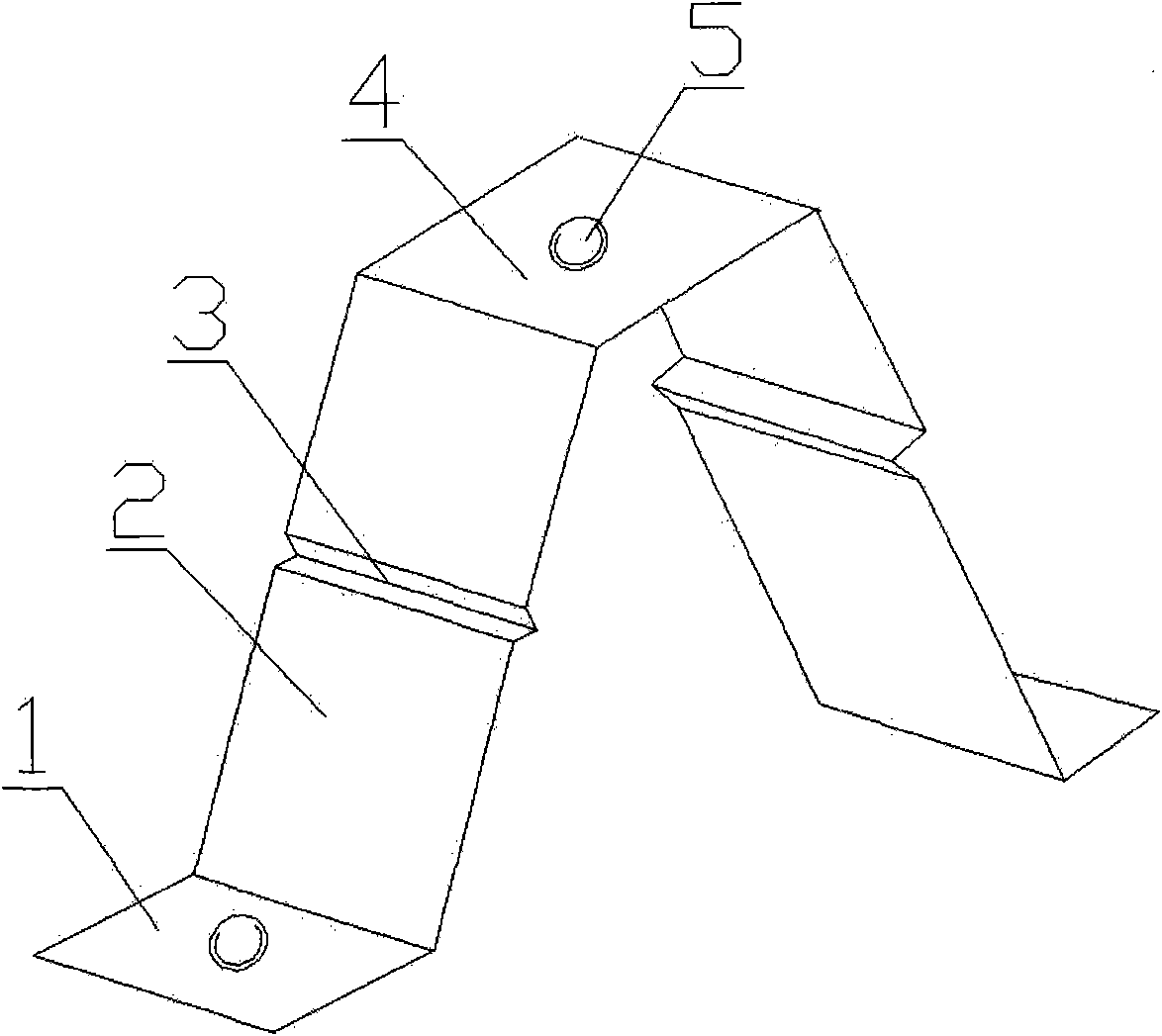
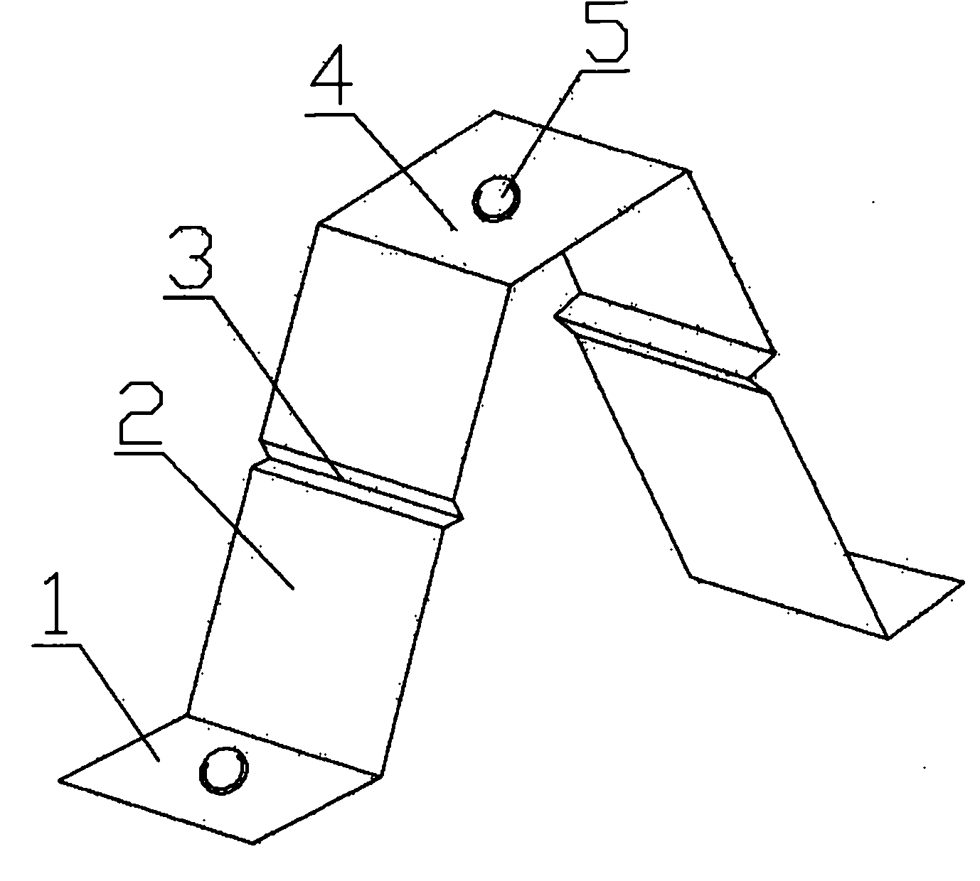
[0025] Such as figure 1 Shown, the technical scheme of the embodiment of the present invention (1) is as follows:

[0026] A wiper shaft fixing bracket, which includes a wiper shaft fixing surface 4 located on the upper layer, supporting surfaces 2 are arranged on both sides of the wiper shaft fixing surface 4, and the lower ends of the supporting surfaces 2 on both sides are respectively connected with bracket fixing surfaces 1, and the lower end of the supporting surface 2 is respectively connected to the inner side of the two bracket fixing surfaces 1; the lateral direction of the supporting surface 2 is provided with an induction groove 3 and the cross section of the induction groove 3 is V-shaped; the bracket fixing surface 1, the supporting surface 2 1. The induction groove 3 and the wiper shaft fixing surface 4 are formed into a "several" shape by stamping; the wiper shaft fixing surface 4 is provided with threaded holes 5; the bracket fixing surface 1 is provided with ...

Embodiment 2

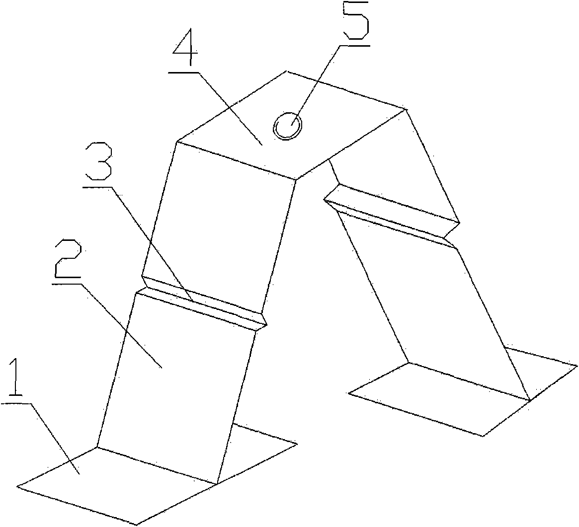
[0035] Such as figure 2 Shown, the technical scheme of the embodiment of the present invention (2) is as follows:

[0036] A wiper shaft fixing bracket, which includes a wiper shaft fixing surface 4 located on the upper layer, supporting surfaces 2 are arranged on both sides of the wiper shaft fixing surface 4, and the lower ends of the supporting surfaces 2 on both sides are respectively connected with bracket fixing surfaces 1, and the lower end of the supporting surface 2 is fixedly connected with the middle of the two bracket fixing surfaces 1 respectively; the supporting surface 2 and the wiper shaft fixing surface 4 are formed as a whole by stamping, and the lower end of the supporting surface 2 is welded to the bracket for fixing On the surface 4; in the transverse direction of the support surface 2, an induction groove 3 is provided, and the cross section of the induction groove 3 is V-shaped; on the wiper shaft fixing surface 4, a threaded hole 5 is provided.

[003...


PUM


Abstract

The invention discloses a wiper shaft fixing support which belongs to the technical field of general motor wipers. The invention has the technical scheme that the wiper shaft fixing support comprises a wiper shaft fixing surface located at the upper layer and two support fixing surfaces located at the lower layer of the wiper shaft fixing surface, and both ends of the wiper shaft fixing surface are respectively connected with the two support fixing surfaces through supporting surfaces. Induction grooves can be arranged on the supporting surfaces in horizontal direction. The lower ends of the supporting surfaces at both sides can be respectively connected with one ends of the support fixing surfaces at both sides. The technical scheme provided by the embodiment of the invention has the advantages that by the support formed by the wiper shaft fixing surface, the supporting surfaces at both sides and the support fixing surfaces at both sides of the lower layer, a wiper shaft can be fixed to motor body parts, such as a motor windshield bottom end rail, a roof drip bottom surface and the like; when the wiper shaft is subject to vertical impact force, the supporting surfaces are forced to bend and deform to absorb impact energy, decrease impact force and reduce the reacting force of the wiper shaft.

Description

technical field [0001] The invention relates to the technical field of wiper blades for general vehicles, in particular to a wiper shaft fixing bracket which is beneficial to pedestrian protection. Background technique [0002] In pedestrian-vehicle traffic accidents, head injury is the leading cause of pedestrian casualties. How to reduce the degree of pedestrian head injury is very important to car design. However, due to its own structure, the wiper shaft is relatively rigid, and it is difficult to deform during the collision process, so it is more aggressive; the wiper shaft is usually directly fixed on the body parts such as the lower beam of the windshield, and the bolts connected to the body when the head hits It is difficult to fail under the axial force, and the wiper shaft almost feeds back to the head with a reaction force as large as the impact force, which has almost no buffering and protection effect on the head, and is likely to cause great damage to the head...

Claims


Application Information

Patent Timeline
IPC IPC(8): B60S1/04
Inventor 赵正王亚军张亮
Owner CHERY AUTOMOBILE CO LTD
Why Eureka
Try Eureka