Pure water machine system with negative pressure stop valve

A shut-off valve and water purifier technology, which is applied in the fields of water/sewage multi-stage treatment, adsorption water/sewage treatment, water/sludge/sewage treatment, etc., which can solve the high pressure of source water and the hidden danger of water purifier system. , increase the cost of the pure water machine system, etc., to achieve the effect of saving costs, improving pressure safety performance, and facilitating installation and application

Inactive Publication Date: 2010-09-15
高新区益腾净水设备研发中心
View PDF0 Cites 0 Cited by
  • Summary
  • Abstract
  • Description
  • Claims
  • Application Information

AI Technical Summary

Problems solved by technology

[0002] At present, the three-way valve or three-way joint of the pure water machine system only has the function of an ordinary three-way, and does not have the function of pressure limiting and filtering. The system causes potential safety hazards. The usual practice is to add a pressure limiting valve in the waterway to solve the problem of high source water pressure.
However, both the pressure reducing valve and the three-way valve are used in the pure water machine system, which increases the cost of accessories and installation required for the pure water machine system
On the other hand, the existing valves do not have a filtering function, so that the booster water shut-off pump with water-cut function can only be installed after the first-stage filter unit of the pure water machine system, that is, the PP surface filter barrel, that is to say, the PP cotton filter The filter barrel is directly connected to the source water pipe network. When the source water pressure is high, the filter barrel has a greater potential safety hazard under pressure; The combination of pressure cut-off valve and booster cut-off pump is a necessary and feasible solution to improve the safety performance of household water purifiers before installing the first-stage filter unit of the pure water machine, that is, the PP cotton filter barrel.

Method used


Image

  • Pure water machine system with negative pressure stop valve
  • Pure water machine system with negative pressure stop valve
  • Pure water machine system with negative pressure stop valve

Examples


Embodiment Construction

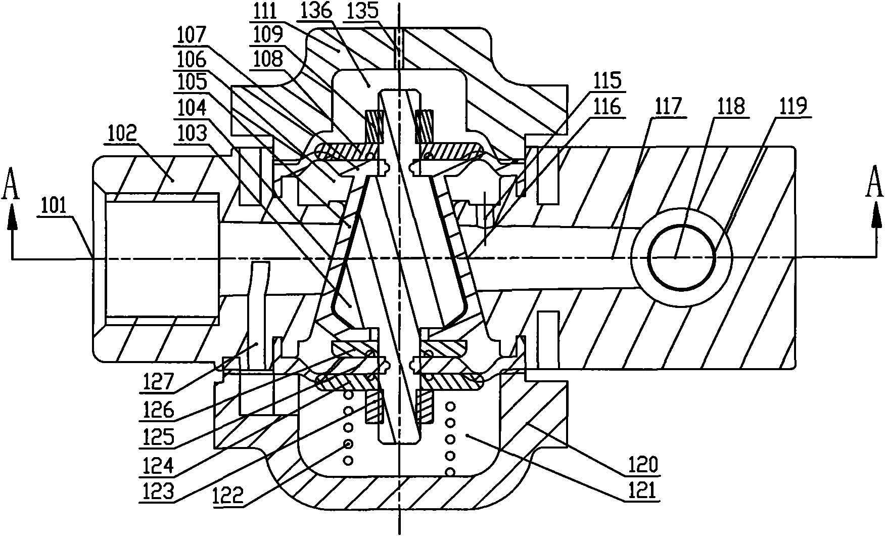
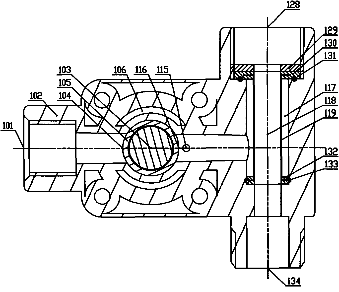
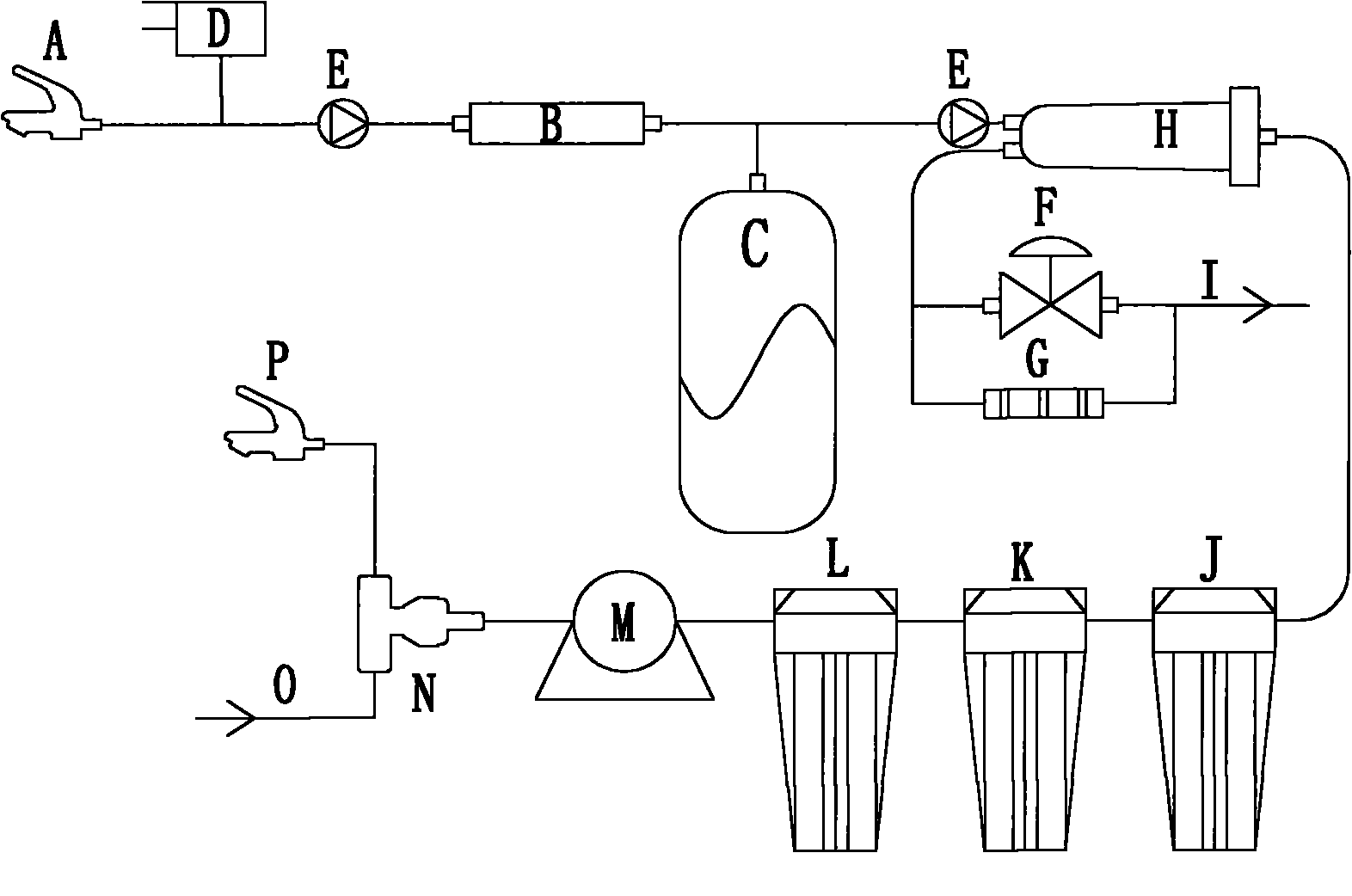
[0017] see Figure 1 to Figure 3As shown, the pure water machine system with a negative pressure shut-off valve includes a negative pressure shut-off valve. The negative pressure shut-off valve includes a valve seat 102, and the valve seat 102 has a source water inlet 134 and a source water outlet 128 connected to each other. , the filtered water outlet 101, the channel where the filtered water outlet 101 is connected with the source water inlet 134 and the source water outlet 128 is provided with a pressure limiting assembly; the source water inlet 134 and the source water outlet 128 are connected A filter screen 119 with a hollow flow channel is provided in the channel, and the two ends of the filter screen 119 respectively pass through the rear ring seal ring 131 of the filter screen, the front ring seal ring 133 of the filter screen and the inner wall of the valve seat 102 to be sealed and fixed; The hollow channel constitutes the pre-filtered source water channel 118, and...


PUM


Abstract

The invention relates to a pure water machine system with a negative pressure stop valve. A source water inlet (134) of the negative pressure stop valve of the system is communicated with source water through a pipeline, a source water outlet (128) is communicated with a source water tap (P) through a pipeline, a filtered water outlet (101) is directly communicated with a water inlet end of a self-absorption booster pump (M) through a pipeline, a filter unit of a pure water machine is not in front of the water inlet end of the self-absorption booster pump (M), and a water outlet end of the self-absorption booster pump (M) is communicated with a water inlet end of a PP cotton filter barrel (L). A water-break protection point of the pure water machine system at shutdown is shifted forward to the front of the PP cotton filter barrel of the pure water machine through the mounting position change of a water-break pump so as to greatly improve the bearing pressure safety performance of each filter unit of the pure water machine.

Description

technical field [0001] The invention relates to a pure water machine system with a negative pressure cut-off valve. Background technique [0002] At present, the three-way valve or three-way joint of the pure water machine system only has the function of an ordinary three-way, and does not have the function of pressure limiting and filtering. The system causes potential safety hazards. The usual practice is to add a pressure limiting valve in the waterway to solve the problem of high source water pressure. However, both the pressure reducing valve and the three-way valve are used in the pure water machine system, which increases the cost of accessories and installation required for the pure water machine system. On the other hand, the existing valves do not have a filtering function, so that the booster water shut-off pump with water-cut function can only be installed after the first-stage filter unit of the pure water machine system, that is, the PP surface filter barrel, ...

Claims


Application Information

Patent Timeline
Patent Type & Authority Applications(China)
IPC IPC(8): C02F9/02C02F1/44C02F1/28
Inventor 隆益腾
Owner 高新区益腾净水设备研发中心
Why Eureka
Try Eureka