Air duct

A technology for air ducts and ducts, which is applied in the field of air ducts and can solve problems such as uneven distribution of wind speed at the air outlet 14

Inactive Publication Date: 2010-09-15
SUNONWEALTH ELECTRIC MACHINE IND
View PDF3 Cites 8 Cited by
  • Summary
  • Abstract
  • Description
  • Claims
  • Application Information

AI Technical Summary

Problems solved by technology

Therefore, the wind speed distribu

Method used


Image

  • Air duct
  • Air duct
  • Air duct

Examples


Embodiment Construction

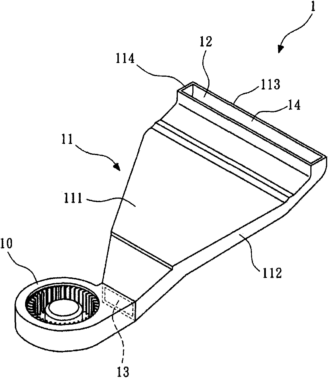
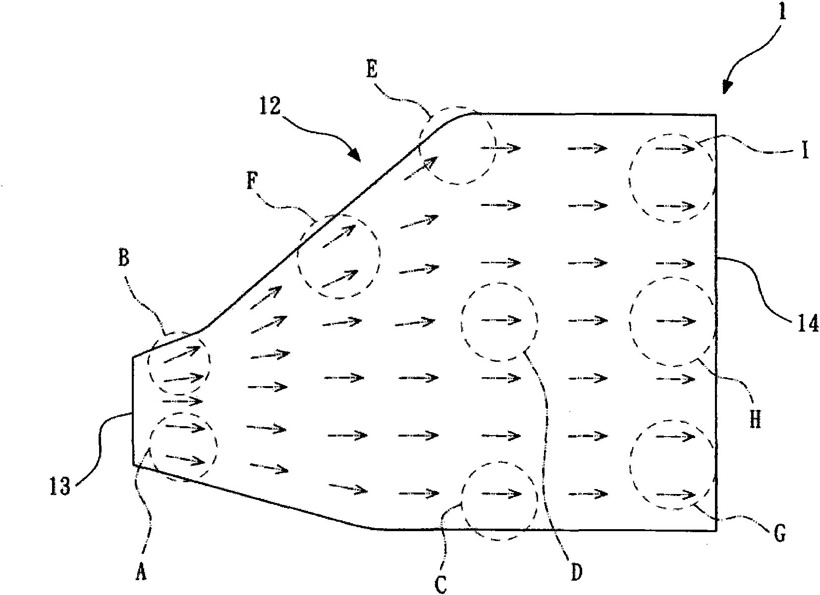
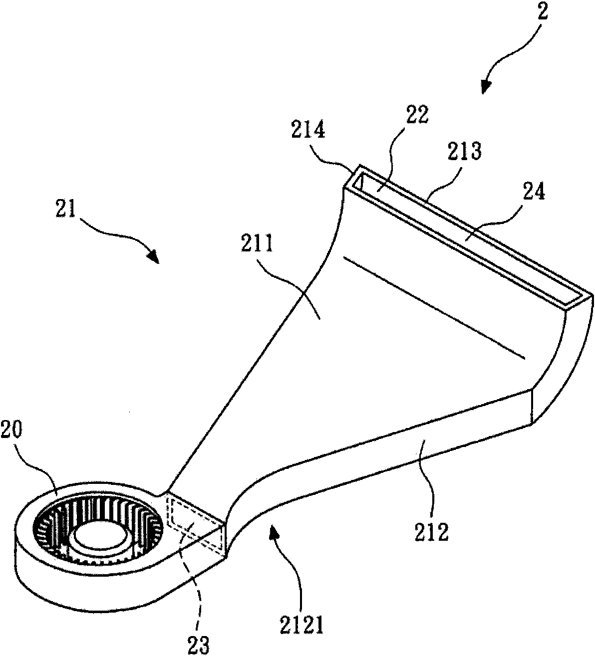
[0011] refer to image 3 and Figure 4 , which respectively show the three-dimensional and top view diagrams of the air duct of the present invention. The air duct 2 includes a body 21 , an air duct 22 , an air inlet 23 , an air outlet 24 and at least one inner constriction 25 .

[0012] The air inlet 23 is used to receive air from the outside (such as the blower fan 20 ). In this embodiment, the air inlet 23 is used for connecting the blower fan 20 . However, it can be understood that the air duct 2 of the present invention can also be applied to other types of fans or other devices that generate wind.

[0013] The air outlet 24 is used to lead out the air from the air inlet 23 , and the area of ​​the air outlet 24 is larger than that of the air inlet 23 . The inner constriction 25 is located between the air inlet 23 and the air outlet 24 , and the area of ​​the inner constriction 25 is smaller than that of the air inlet 23 .

[0014] In this embodiment, the air duct 2 i...


PUM


Abstract

The invention relates to an air duct, comprising an air inlet, an air outlet and at least an inward-retracted opening. The air inlet is used for receiving air from outside, and the air outlet is used for guiding the air out from the air inlet. The area of the air outlet is greater than that of the air inlet. The inward-retracted opening is located between the air inlet and the air outlet. The area of the inward-retracted opening is smaller than that of the air inlet. Therefore, the air from the air inlet is contracted gradually and expanded gradually after passing through the inward-retracted opening so that wind speed of the air outlet of the air duct is distributed uniformly, the pipeline loss can be reduced, and the air quantity at the air outlet can be increased.

Description

technical field [0001] The invention relates to an air guide pipe, in particular, to an air guide pipe with an inner constriction. Background technique [0002] refer to figure 1 , showing a schematic perspective view of an air duct conventionally used for a blower fan. The air duct 1 includes a body 11 , an air duct 12 , an air inlet 13 and an air outlet 14 . The air duct 1 is generally flat. The body 11 is surrounded by a first side wall 111 , a second side wall 112 , a third side wall 113 and a fourth side wall 114 in sequence, and an air duct 12 is formed inside the body 11 . The air inlet 13 and the air outlet 14 are respectively located at two ends of the main body 11 . The air inlet 13 is used to receive air from the outside (such as the blower fan 10 ). The air outlet 14 is used for leading out the air from the air inlet 13 . The area of ​​the air outlet 14 is larger than the area of ​​the air inlet 13 . The air duct 12 communicates with the air inlet 13 and t...

Claims


Application Information

Patent Timeline
IPC IPC(8): F04D29/44
Inventor 洪银树陈泓翔方议乐
Owner SUNONWEALTH ELECTRIC MACHINE IND
Why Eureka
Try Eureka