Lens

A lens and lens technology, applied in the field of projection lens, can solve the problem that the lens is difficult to achieve dustproof design, and achieve the effect of good optical imaging quality

Active Publication Date: 2010-09-15
YOUNG OPTICS
View PDF6 Cites 28 Cited by
  • Summary
  • Abstract
  • Description
  • Claims
  • Application Information

AI Technical Summary

Problems solved by technology

[0004] Curved mirrors can be divided into convex mirrors and concave mirrors. The size of the convex mirror is usually larger, which makes it difficult to achieve dustproof design for the lens.

Method used


Image

  • Lens
  • Lens
  • Lens

Examples


Embodiment Construction

[0065] The following descriptions of various embodiments refer to the accompanying drawings to illustrate specific embodiments in which the present invention can be practiced. The direction terms mentioned in the present invention, such as "up", "down", "front", "rear", "left", "right", etc., are only referring to the directions of the drawings. Accordingly, the directional terms are used to illustrate, not to limit, the invention.

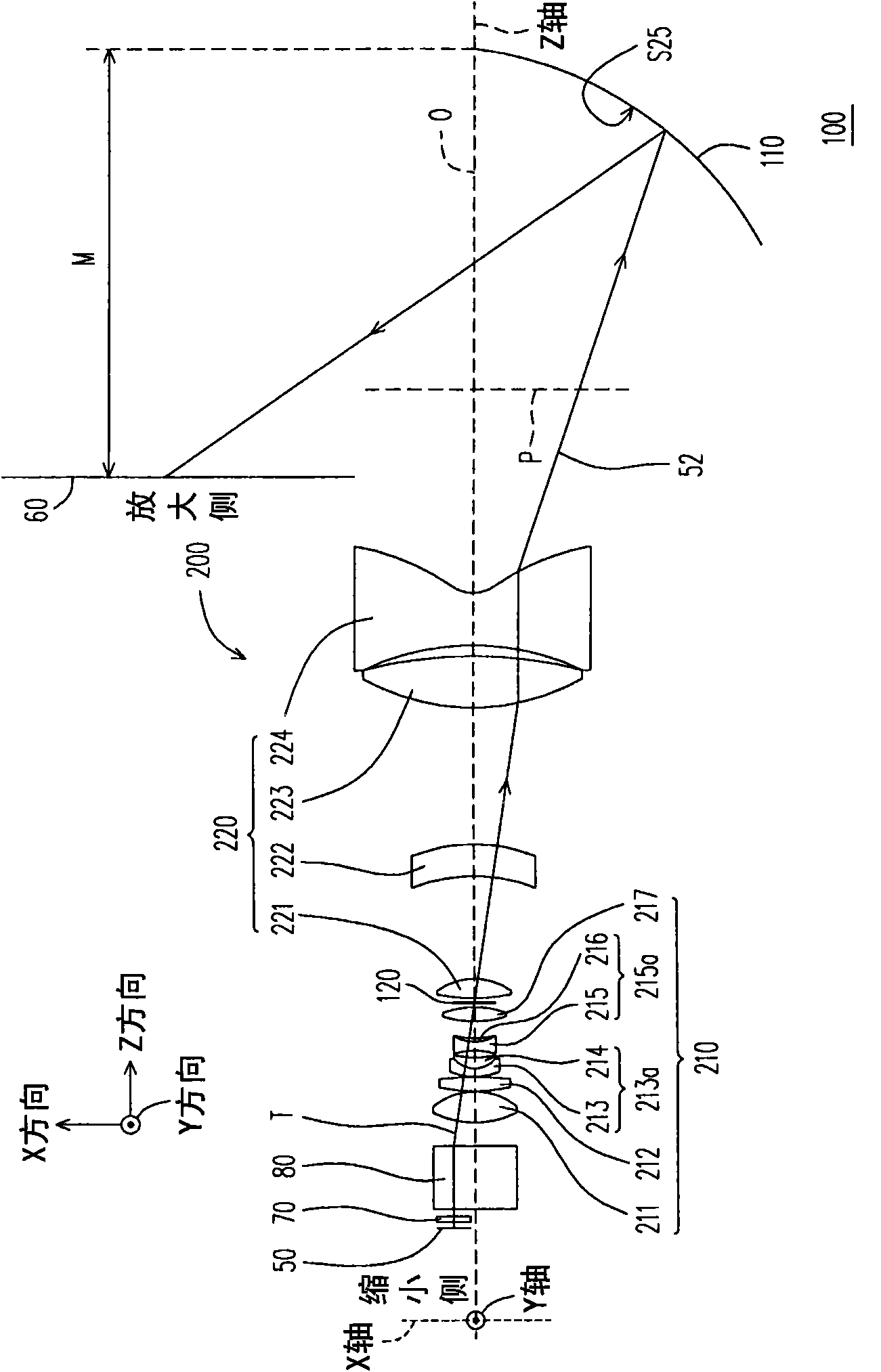
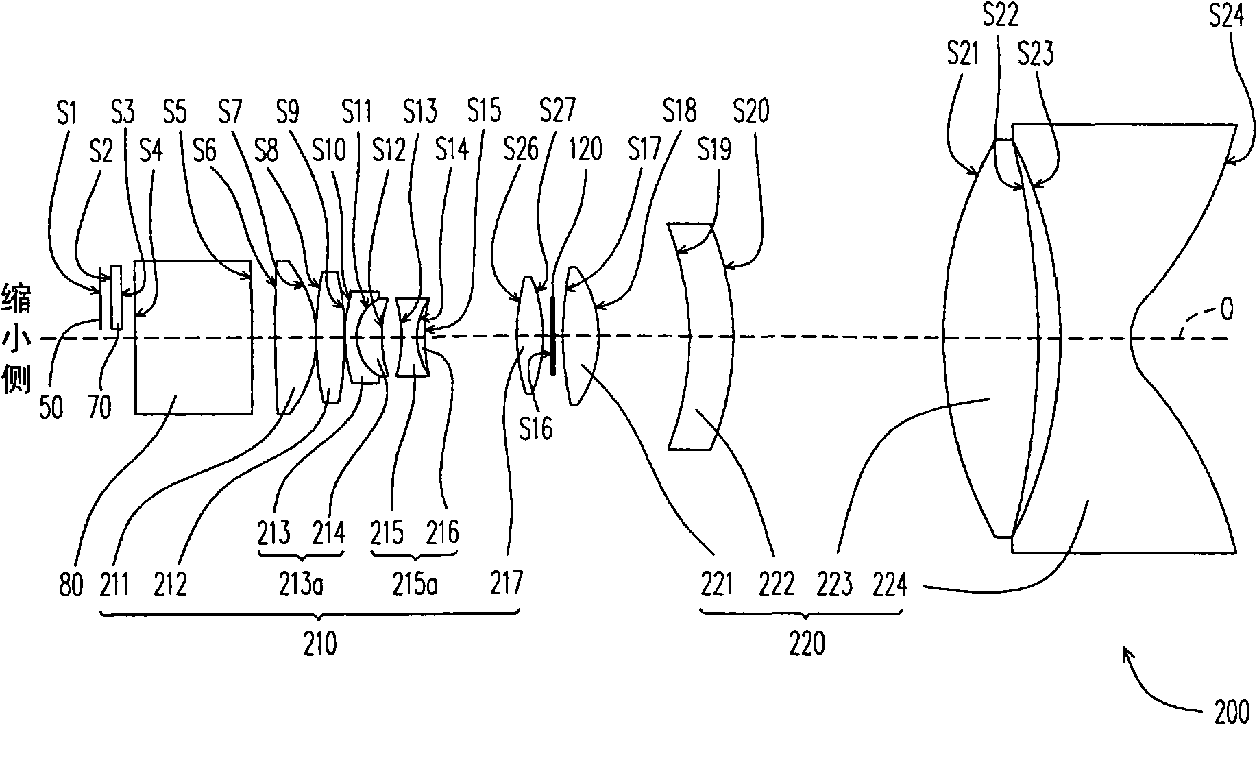
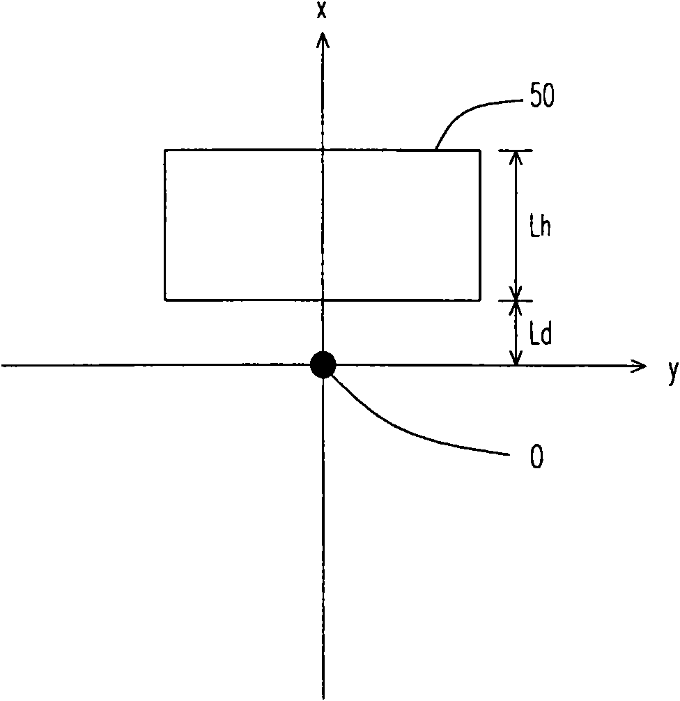
[0066] Figure 1A is a structural schematic diagram of a lens according to an embodiment of the present invention, and Figure 1B for Figure 1A Schematic diagram of the structure of the lens group in the lens. refer to Figure 1A and Figure 1B , the lens 100 of this embodiment is suitable for imaging a first image plane 50 on a zoom-in side to a zoom-in side. In this embodiment, the lens 100 may be a fixed-focus lens. In this embodiment, the first image plane 50 is, for example, the active surface of the light valve. The image beam 52 emitte...


PUM


Abstract

A lens adapted to image a first image plane at a reduced side onto a magnified side is provided. The lens has an optical axis. The lens includes a lens group and a concave reflective mirror. The lens group is disposed in the light path between the reduced side and the magnified side. The concave reflective mirror is disposed in the light path between the lens group and the magnified side. The offset of the first image plane with respect to the optical axis is greater than 100%. The throw ratio of the lens is less than 0.3.

Description

technical field [0001] The invention relates to a lens, and in particular to a projection lens. Background technique [0002] With the development of display technology, a new generation of displays such as liquid crystal displays (liquid crystal displays, LCDs), plasma displays (plasma display panels, PDPs) and projection apparatuses (projection apparatus) have gradually replaced traditional cathode ray tubes (cathode ray tubes). ray tube, CRT). Among them, flat panel displays such as liquid crystal displays and plasma displays can occupy a large household market due to their thinner thickness. On the other hand, the projection device can occupy a certain market proportion because it can provide a super-large-sized screen (for example, larger than 52 inches) at a relatively low cost. In addition, the super-sized screen can be watched by many people, which is helpful for the conduct of meetings, the presentation of presentations or the display of teaching data. This is one...

Claims


Application Information

Patent Timeline
Patent Type & Authority Applications(China)
IPC IPC(8): G02B17/08
Inventor 陈松楠廖龙盛许雅伶陈昭舜
Owner YOUNG OPTICS
Why Eureka
Try Eureka