
Device and network system

一种设备、网络的技术,应用在经由网络的电力供给领域,能够解决难以适用网络结构、设定麻烦等问题

Active Publication Date: 2010-09-15
OMRON CORP
View PDF3 Cites 25 Cited by
  • Summary
  • Abstract
  • Description
  • Claims
  • Application Information

AI Technical Summary

Problems solved by technology

In order to predetermine the function in this way, not only the setting becomes troublesome, but also if a failure occurs in the communication port for power reception or the network cable connected to the communication port, even if the communication port set for power supply is Yes, there is also the problem of not being able to receive power supply using the communication port used for power supply
Furthermore, as disclosed in Patent Document 1, the connection method of each device is limited to a network structure such as power supply from upstream to downstream, such as a series structure, a radial (hub and spoke) structure, or a combination thereof, and it is difficult to Applicable to problems in network systems where multiple communication ports may be able to receive power, such as a ring-type network structure

Method used


Image

  • Device and network system
  • Device and network system
  • Device and network system

Examples


Embodiment Construction

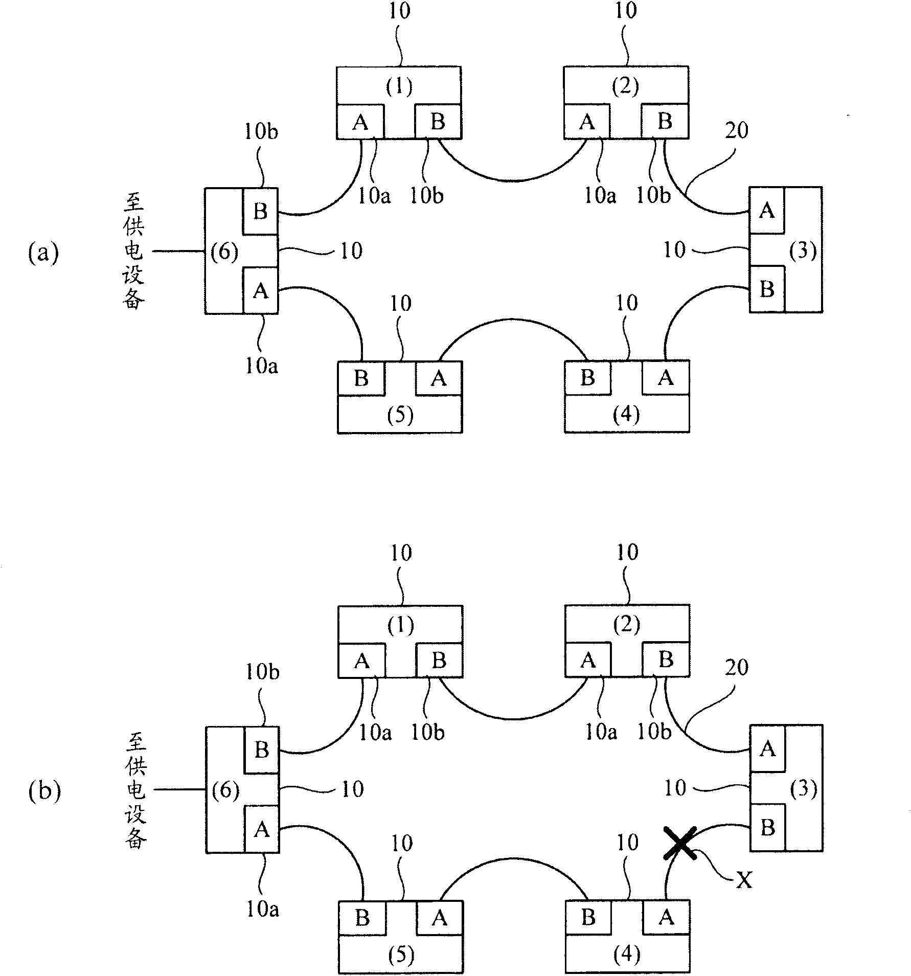
[0031] figure 1 Represents an example of a network system. This network system adopts a configuration in which devices 10 having a plurality of communication ports (in the present embodiment, the first communication port 10a and the second communication port 10b) are arranged in a ring type via a network cable 20. That is, the communication ports of adjacent devices 10 are connected by the network cable 20. This device 10 is based on EtherCAT (registered trademark Ethernet for Control Automation Technology: Ethernet control automation technology) which is one of the industrial network standards. EtherCAT (registered trademark) is a high-speed fieldbus system based on Ethernet (registered trademark).

[0032] E.g figure 1 As shown in (b), this ring-type connection method can use another path to continue data communication even when the network cable 20 at one location (point X in the figure) is cut. Therefore, the device 10 has a function of monitoring whether the network cable ...


PUM


Abstract

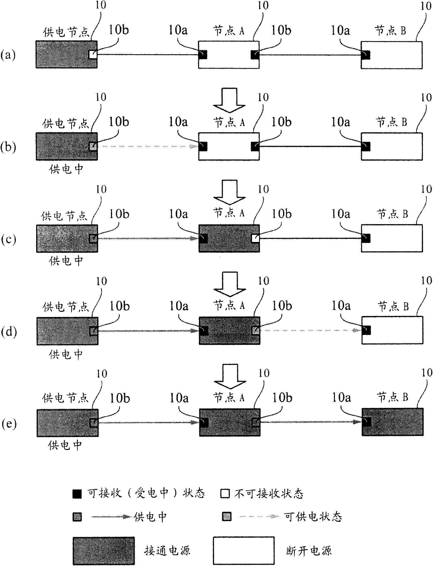
Provided are a device and a network system, wherein plural communication ports are switched appropriately between a power receiving port and a power feeding port, thereby dealing with supply of electric power through a network in various network configurations. Plural devices (10) are connected to a network cable (20) to form a network system. In an initial state before power receiving, all plural communication ports (10a,10b) of the device (10) are put in to a power receiving enabling state. When the electric power is supplied from one of the communication ports, other communication ports are put into a power receiving disabling state. The device (10) feeds part of the received electric power to another adjacent device (10) by utilizing the communication port (10a,10b) put into the power receiving disabling state. The supply of electric power can sequentially be performed from the device that receives the supply of electric power from an external power feeding installation (6) to an adjacent device (1,5), and finally all the devices (1-6) receive the supply of electric power through the network.

Description

Technical field [0001] The present invention relates to equipment and network systems that constitute a network, and more specifically, relates to a technical improvement of power supply to the equipment via the network. Background technique [0002] PoE (Power over Ethernet (registered trademark): Power Ethernet) is a technology for power supply using an Ethernet (registered trademark) cable. By using this PoE, it is possible to easily supply power to devices installed in locations where it is difficult to directly supply power. In addition, this PoE can transmit both data and power on the cable, so there is no need to separately arrange the cable for data communication and the cable for power supply, and it can be easily wired when installing various devices that constitute a network system on site. deal with. [0003] In addition, in a network system having a power supply function such as this PoE, a technique has been proposed in which a device connected to the network suppli...

Claims


Application Information

Patent Timeline
Patent Type & Authority Applications(China)
IPC IPC(8): H04L12/10
CPCH04L12/42H04L12/40045H04B3/44H04L12/10
Inventor 户川智史
Owner OMRON CORP
Learn More