Damper and door handle with the same

An air damping and cylinder technology, applied in the field of door handles and dampers

Inactive Publication Date: 2012-11-28
NIFCO INC
View PDF2 Cites 1 Cited by
  • Summary
  • Abstract
  • Description
  • Claims
  • Application Information

AI Technical Summary

Problems solved by technology

In addition, in Patent Document 2, a check valve is provided to connect the two air chambers divided by the piston, and the check valve is opened and closed according to the moving direction of the piston to obtain the presence or absence of the damping effect.

Method used


Image

  • Damper and door handle with the same
  • Damper and door handle with the same
  • Damper and door handle with the same

Examples


no. 1 approach

[0079] The air damper according to the first embodiment of the present invention will be described below.

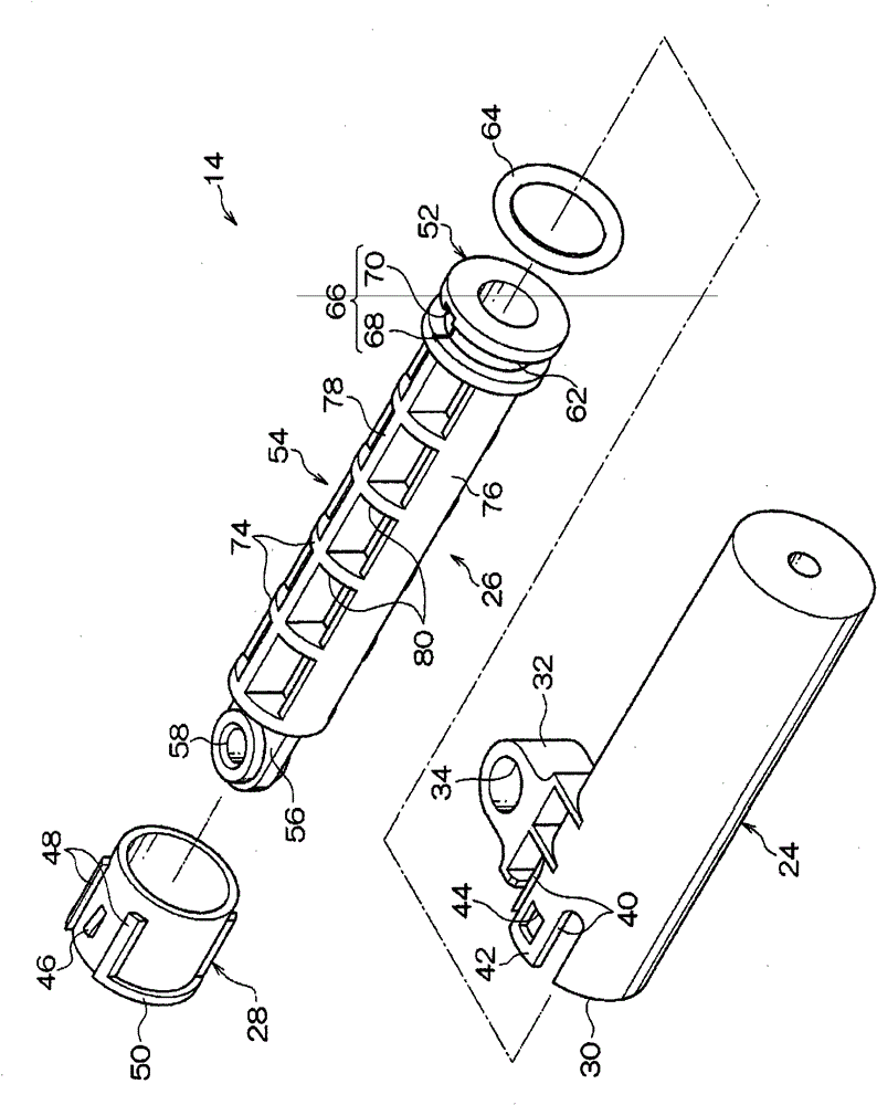
[0080] Such as image 3 As shown, the air damper 14 is roughly divided into a cylinder 24 , a piston member 26 and a sleeve 28 , and the piston member 26 accommodated in the cylinder 24 is prevented from falling off by the sleeve 28 .

[0081] cylinder

[0082] First, the cylinder 24 will be described. Such as figure 2 and image 3 As shown, the cylinder 24 is formed in a bottomed cylindrical shape, and an opening 30 is provided at one end. On the opening portion 30 side of the cylinder 24 , a connecting piece (first connecting mechanism) 32 protruding from the outer peripheral surface of the cylinder 24 is provided.

[0083]A connecting hole (first connecting mechanism) 34 is formed in the central portion of the connecting piece 32 . A shaft portion (first coupling mechanism) 36 provided on the lower surface side of the main body portion 16 can be inserted throug...

no. 2 approach

[0118] Next, an air damper according to a second embodiment of the present invention will be described. In addition, the content substantially the same as that of the first embodiment will not be briefly described.

[0119] Such as Figure 7 As shown, a plurality of substantially prismatic through-holes 94 penetrating in a direction perpendicular to the axial direction of the cylindrical piston rod 92 are provided. Thereby, the wall thickness of the piston rod 92 can be made substantially uniform, the shrinkage cavity of the outer peripheral wall of the piston rod 92 can be suppressed, and the precision of the outer diameter dimension of the piston rod 92 can be improved. In addition, although not shown, a hollow portion may be provided in the axial direction of the piston rod.

no. 3 approach

[0121] Next, an air damper according to a third embodiment of the present invention will be described. In addition, descriptions of substantially the same contents as those of the first embodiment will be omitted.

[0122] In the first embodiment, the sleeve 28 is inserted into the opening 30 of the cylinder 24, and as Figure 8 As shown, if the outer diameters of the piston 100 and the piston rod 102 are the same, the pipe sleeve may not be required. Because the opening and closing angle of operating rod 18 has been stipulated, so the stroke of piston 100 just stipulates, even if there is no sleeve, piston 100 also can not come off from cylinder 104.

[0123] Also, at this time, the gap between the outer peripheral wall of the piston rod 102 and the inner peripheral wall of the cylinder 104 is reduced. Here, since no sleeve is used, as Figure 5A As shown, it is not necessary to make the distance between the disc portion 74 of the piston rod 54 below the depth (H) of the t...


PUM


Abstract

When there is a gap between a circular plate (152) of a rod (150) and a cap (28), if a piston (52) is pushed into a cylinder (24), a large amount of air is discharged from the inside of the cylinder (24) through the gap, causing noise generated in the cylinder (24) to leak to the outside. However, in a damper of this invention, the gap between the rod (54) and the cap (28) is made as small as possible, and as a result, the amount of air discharged from the inside of the cylinder (24) when the piston (52) is pushed into the cylinder (24) is extremely small.

Description

technical field [0001] The invention relates to a damper and a door handle with the damper. Background technique [0002] Conventionally, an air damper is known to obtain a damping effect by compressing air in a cylindrical cylinder with a piston. [0003] For example, in Patent Document 1, an annular groove is provided on the outer peripheral surface of the piston that moves in the cylinder, and a seal ring that is in sliding contact with the inner peripheral wall of the cylinder is installed in the groove so that it can move in the groove, thereby One direction produces braking force. In addition, in Patent Document 2, a check valve is provided which communicates the two air chambers divided by the piston, and the presence or absence of the damping effect is obtained by opening and closing the check valve according to the moving direction of the piston. Furthermore, in Patent Document 3, a conical orifice is provided in the central portion of the piston, and the damping ...

Claims


Application Information

Patent Timeline
Patent Type & Authority Patents(China)
IPC IPC(8): F16F9/32B60J5/04E05B1/00F16F9/02F16F9/34
CPCE05B85/12E05B85/13E05B77/42F16F9/0227F16F9/0218F16F9/516Y10T292/57B60J5/04B60J5/00
Inventor 濑户康彦神保直人
Owner NIFCO INC
Why Eureka
Try Eureka