Construction machine

a construction machine and construction technology, applied in the direction of machines/engines, mechanical equipment, transportation and packaging, etc., can solve the problems of increasing increasing the noise leakage of the pump to the outside, and unable to obtain sufficient sound absorption effect, etc., to reduce the amount of used sound absorbing materials, improve the air discharge performance, and reduce the effect of airflow

Active Publication Date: 2015-07-28
KOBELCO CONSTR MASCH CO LTD
View PDF28 Cites 0 Cited by
  • Summary
  • Abstract
  • Description
  • Claims
  • Application Information

AI Technical Summary

Benefits of technology

[0022]An object of the present invention is to suppress pump noise leakage from a construction machine while improving an air discharge performance of a lower airflow that flows under an engine, and when a sound absorbing material is provided, to facilitate device installation while securing a superior sound absorption effect with a small amount of the sound absorbing material.

Problems solved by technology

Hence, an increase in pump noise leakage to the outside, including “direct sound” emitted directly to the exterior of the exhaust chamber 20 from the hydraulic pump 14, occurs.
Furthermore, in the conventional technique described above, when an attempt is made to reduce pump noise leakage using a sound absorbing material such as glass wool, a sufficient sound absorption effect cannot be obtained unless the sound absorbing material is provided over a wide range of the exhaust chamber 20, including the vicinity of the exhaust ports 22, 23.
Therefore, an amount of used sound absorbing material increases, leading to an increase in cost, and moreover, when the sound absorbing material is provided over a wide range of the exhaust side, devices disposed on the exhaust side, not shown in the drawings, cannot easily be installed due to limitations on sizes and positions of the devices.

Method used


Image

  • Construction machine
  • Construction machine
  • Construction machine

Examples


first embodiment

[0034](First Embodiment)

[0035]First, a first embodiment of the present invention will be described with reference to FIGS. 1 to 5.

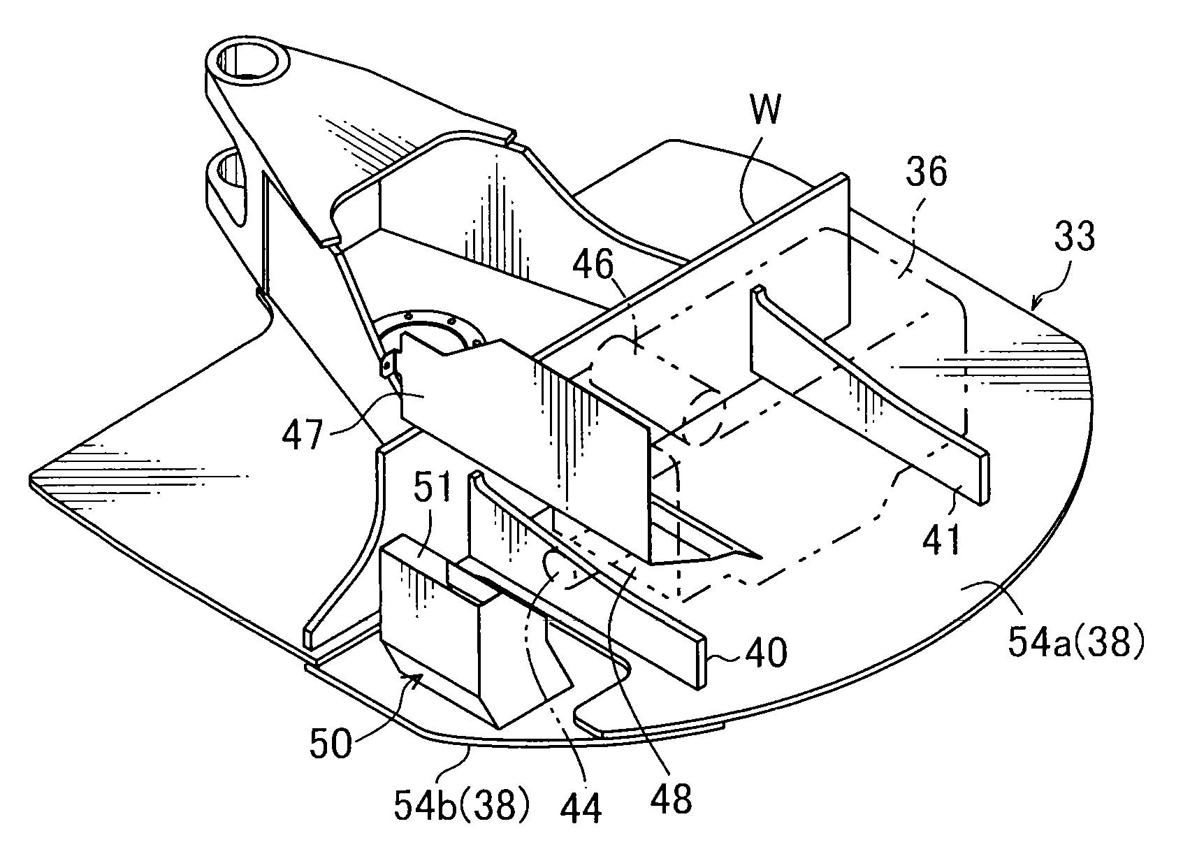
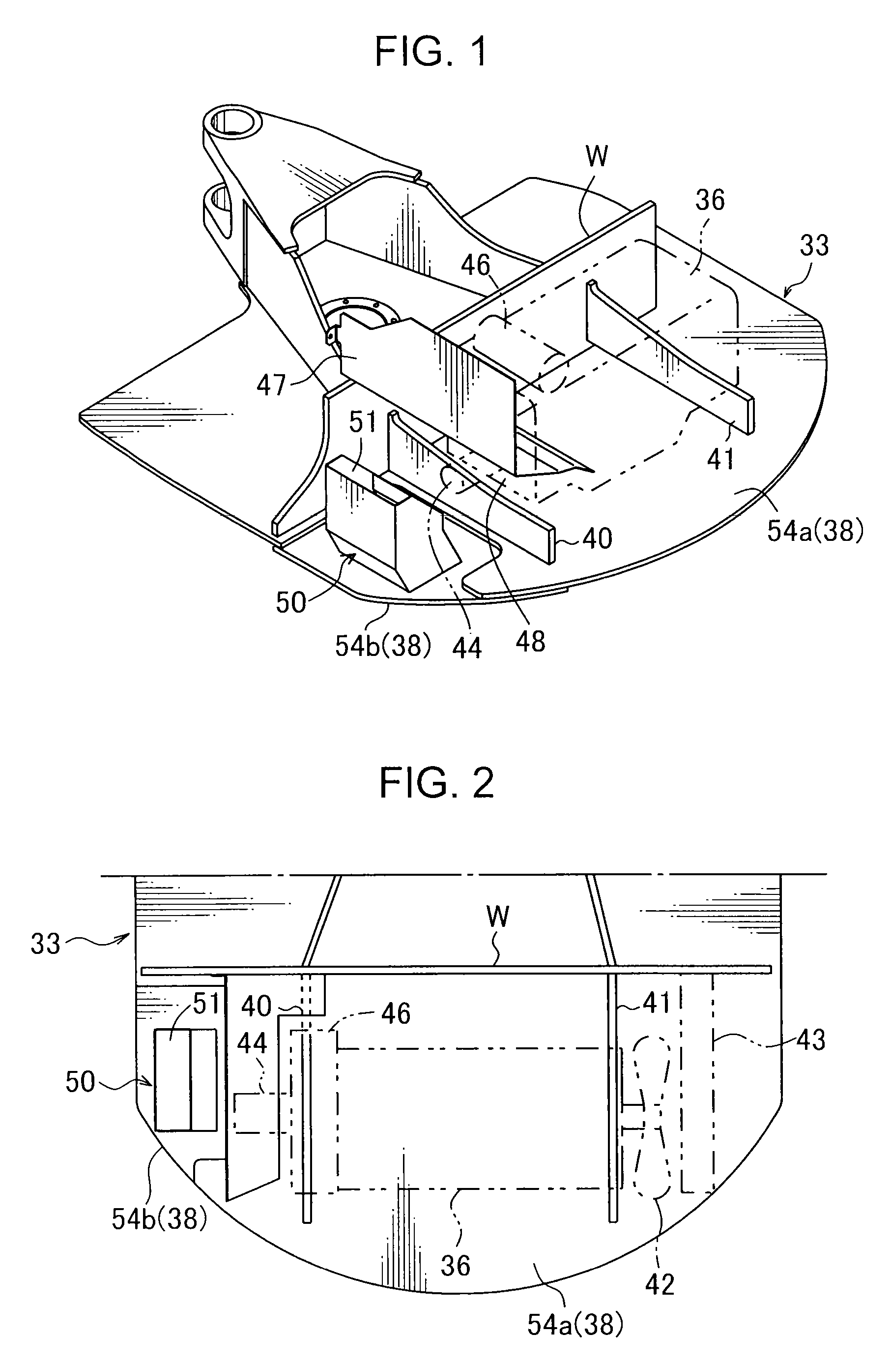
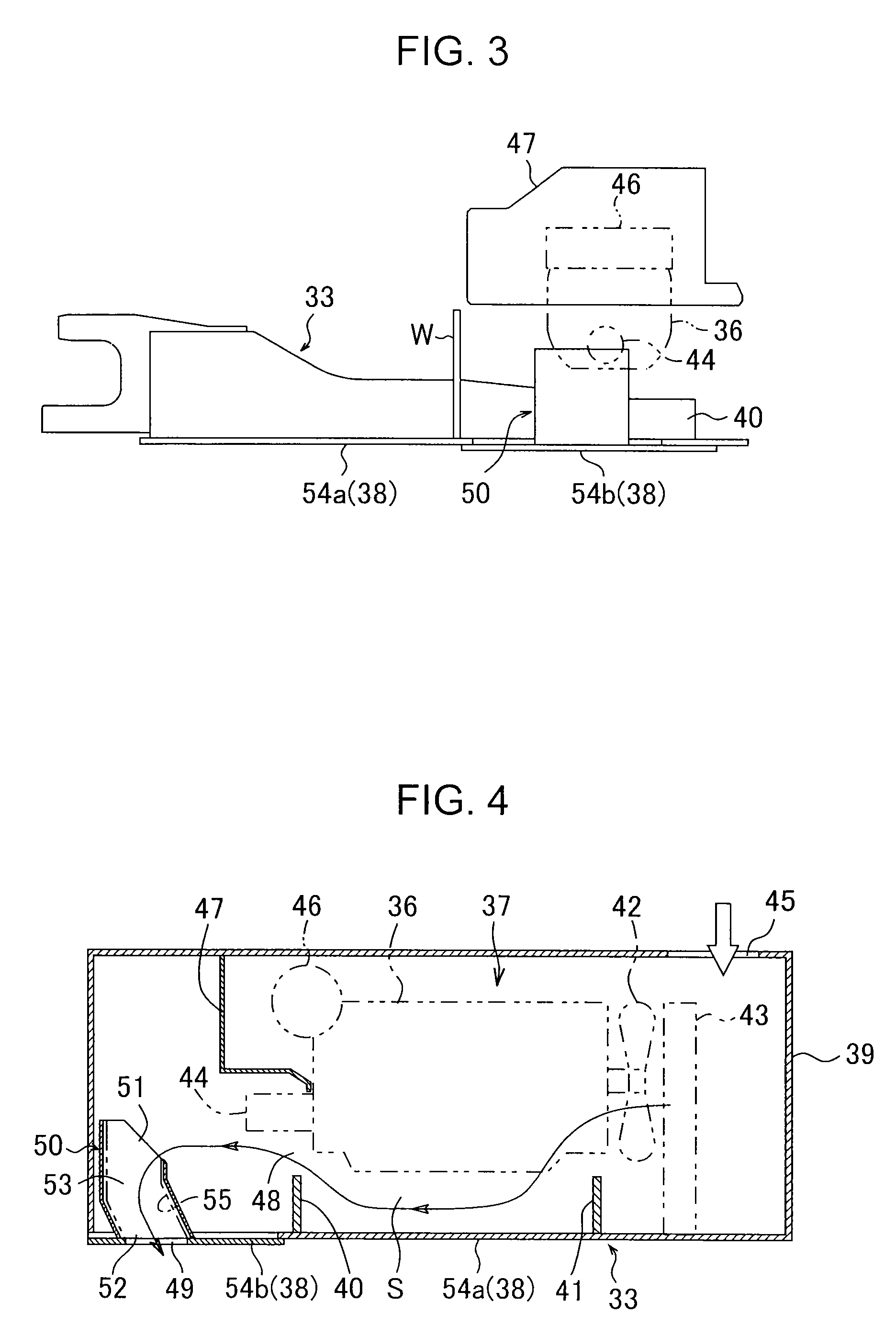
[0036]In the first embodiment, following points (i) to (v) are identical to the background art and conventional technique illustrated in FIGS. 8 and 9.[0037](i) An engine room 37 (see FIG. 4) housing an engine 36 is provided in a rear portion of an upper frame 33.[0038](ii) The engine room 37 is a space that is long in a left-right direction and formed by being surrounded by a base plate 38 of the upper frame 33, an engine guard member 39 such as a panel material, a counterweight (not shown) attached to a rear end portion of the upper frame 33, and so on. The base plate 38 of the upper frame 33 corresponds to a floor forming a bottom surface of the engine room 37. The engine 36 is disposed in the engine room 37 via a mounting member, not shown in the drawing, so as to extend in the left-right direction.[0039](iii) A left-right pair of vertical plates 40, ...

second embodiment

[0062](Second Embodiment)

[0063]Next, a second embodiment of the present invention will be described with reference to FIG. 6.

[0064]Note that only parts of the second embodiment and a following third embodiment that differ from the first embodiment will be described.

[0065]In the first embodiment, the exhaust duct 50 is mounted on the duct base plate 54b such that the exhaust duct 50 is located at a position which is separated slightly inward from the outer periphery of the left rear end portion of the upper frame 33. In the second embodiment, on the other hand, the exhaust duct 50 is provided on an inner side of the outer periphery of the engine room 37 so as to extend along the substantially arc-shaped outer periphery of the engine room 37 disposed in the rear end portion of the upper frame 33.

[0066]According to this configuration, the outer peripheral shape of the engine room 37 does not have to be modified in order to dispose the exhaust duct 50, and therefore large design modific...

third embodiment

[0067](Third Embodiment)

[0068]Next, a third embodiment of the present invention will be described with reference to FIG. 7.

[0069]In the third embodiment, the exhaust duct 50 includes an upper side portion 50a that extends horizontally in the left-right direction, a lower side portion 50b disposed below and parallel to the upper side portion 50a via an interval, and a vertical side portion 50c disposed perpendicularly to the upper side portion 50a and the lower side portion 50b so as to connect left end portions on identical sides of the upper side portion 50a and the lower side portion 50b to each other. Hence, the exhaust duct 50 is formed in the approximate shape of a U tipped onto its side when seen from a back surface. Further, the exhaust duct 50 is disposed such that the hydraulic pump 44 is sandwiched between the upper side portion 50a and the lower side portion 50b.

[0070]Note that the air inlet 51 of the exhaust duct 50 is formed over an upper wall, a right side wall and a ...


PUM


Abstract

A construction machine includes an exhaust duct for discharging a lower airflow to the exterior of an engine room. An air inlet for introducing air into the exhaust duct is provided in an upper portion of the exhaust duct, and an air outlet for discharging the air from the exhaust duct is provided in a lower portion of the exhaust duct. An air passage is formed in the interior of the exhaust duct between the air inlet and the air outlet. The exhaust duct is disposed on an exhaust side of the engine room such that the air introduced into the air passage in the exhaust duct through the air inlet is discharged below the engine room from the air outlet through a discharge port, and such that a hydraulic pump provided on the exhaust side of the engine room is shielded from the discharge port by the exhaust duct.

Description

BACKGROUND OF THE INVENTION[0001]1. Field of the Invention[0002]The present invention relates to a construction machine such as a digger, in which an exhaust structure is provided to discharge a lower airflow that flows under an engine in an engine room.[0003]2. Background Art[0004]The background art will now be described, using a digger as an example of a construction machine.[0005]As shown in FIG. 8, a digger includes a lower propelling body 1, an upper slewing body 2 that is carried on the lower propelling body 1 to be free to slew, various pieces of equipment and various devices carried on an upper frame 3 serving as a base of the upper slewing body 2, and a work attachment (also referred to as a digging attachment) 5 attached to a front portion of the upper frame 3. The various pieces of equipment carried on the upper frame 3 include a cabin 4. In FIG. 8, CW denotes a counterweight attached to a rear end portion of the upper frame 3.[0006]Note that in this specification, a posi...

Claims


Application Information

Patent Timeline
Patent Type & Authority Patents(United States)
IPC IPC(8): B60K11/08F01P11/10B62D25/08E02F9/08B60K11/00B60K11/06B60K11/04F01P11/12F01P1/00
CPCE02F9/0866B60K11/04B60K11/06B60K11/08B62D25/082F01P11/10F01P11/12B60Y2200/412F01P2001/005
Inventor TSUCHIHASHI, TOMOYUKIUEDA, KAZUHIRONUMASAWA, MASARU
Owner KOBELCO CONSTR MASCH CO LTD
Why Eureka
Try Eureka