
Touch panel and electronic device

A touch panel and electrode technology, applied in electrical digital data processing, instruments, calculations, etc., can solve the problems of reduced pressure detection accuracy and leakage, and achieve high-precision pressure detection, reduce stray capacity, and suppress noise leakage.

Active Publication Date: 2016-11-16
MURATA MFG CO LTD
View PDF7 Cites 2 Cited by
  • Summary
  • Abstract
  • Description
  • Claims
  • Application Information

AI Technical Summary

Problems solved by technology

[0009] However, in the case of configuring the touch panel 300A in this way, the electrostatic touch panel unit and the pressure sensor unit are very close to each other, so electrical coupling occurs between the electrostatic touch panel unit and the pressure sensor unit.
Therefore, the pulse signal for driving the electrostatic touch panel part may leak to the pressure sensor part as noise, and the precision of pressure detection may decrease.

Method used


Image

  • Touch panel and electronic device
  • Touch panel and electronic device
  • Touch panel and electronic device

Examples


Embodiment Construction

[0046] A touch panel according to a first embodiment of the present invention will be described with reference to the drawings. In the following description, one main surface of each film is referred to as "top surface", and the other main surface of each film is referred to as "bottom surface".

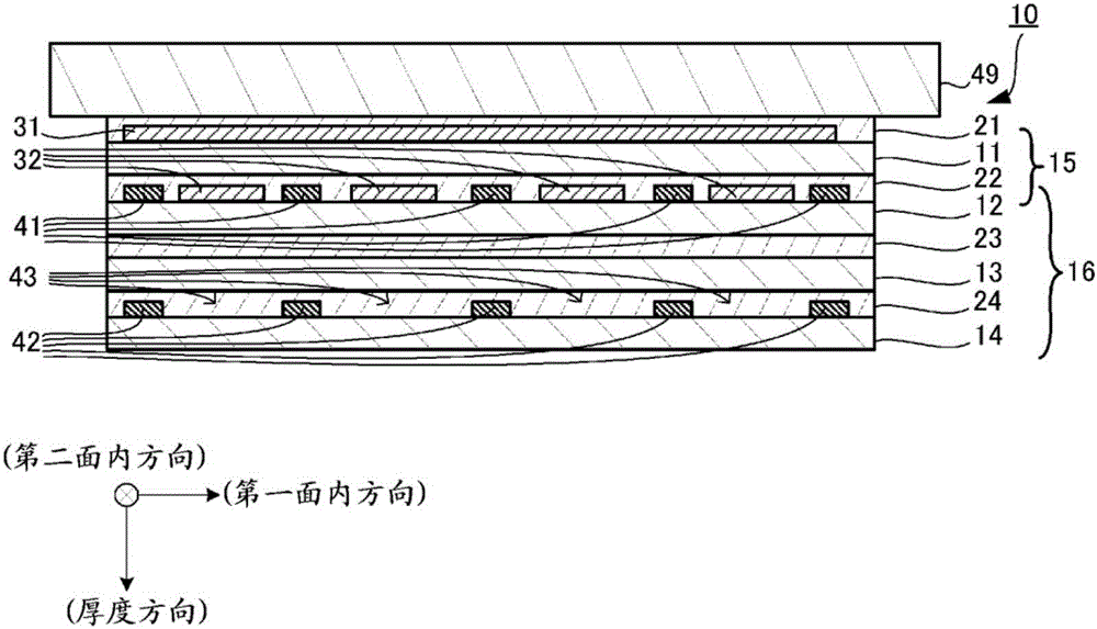
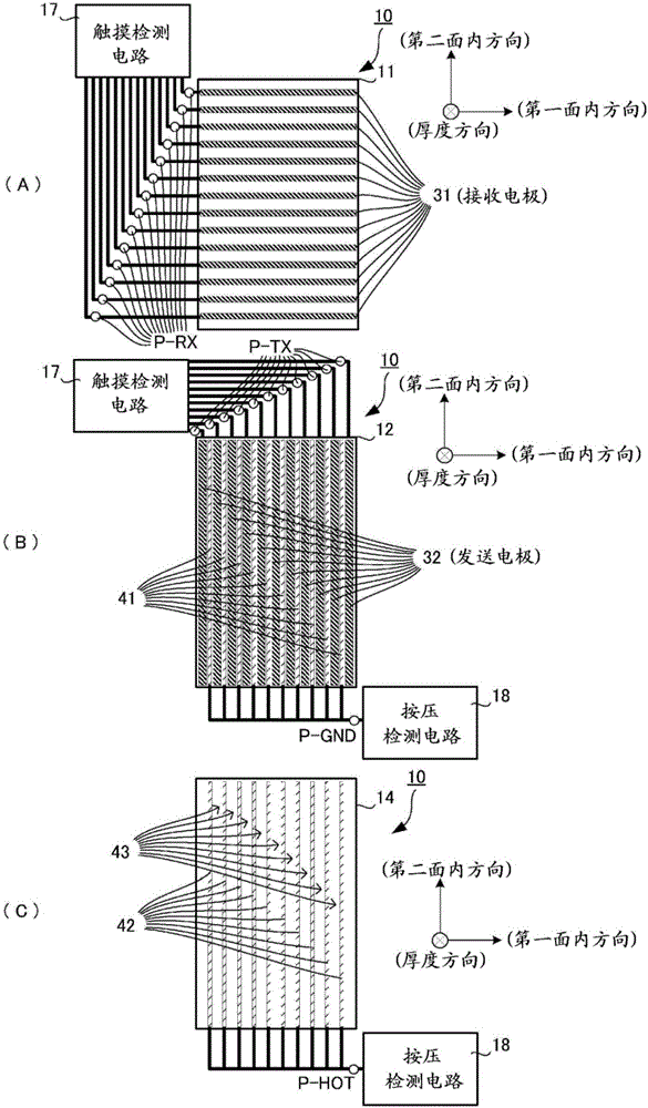
[0047] figure 1 It is a side cross-sectional view of touch panel 10 according to this embodiment. figure 2 It is a plan view showing an electrode pattern of a film included in the touch panel 10 . should be explained, figure 2 The electrode pattern shown is just an example, and the number and shape of each electrode are not limited to one, and can be appropriately changed according to specifications.

[0048] The touch panel 10 is used by being pasted on a non-conductive elastic plate such as glass, acrylic, or polycarbonate. Here, the touch panel 10 is attached to the back side of the cover glass 49 of the display unit of the electronic device, and detects touch operation and...


PUM


Abstract

Provided is a technology with which accuracy of pressing-force detection can be improved even if the total number of films in a touch panel is reduced. This touch panel (10) is provided with an electrostatic-type touch panel unit (15) and a pressing-force sensor unit (16). The electrostatic-type touch panel unit (15) is provided with a film (11), and touch-panel electrodes (31, 32). The pressing-force sensor unit (16) is provided with a film (13), and pressing-force-sensor electrodes (41, 42). The pressing-force-sensor electrodes (41) are provided in the same electrode layer as the touch-panel electrodes (32). An electrode layer having the pressing-force-sensor electrodes (42) provided therein has, provided in positions facing the touch-panel electrodes (32), sections where the pressing-force-sensor electrodes (42) are not formed.

Description

technical field [0001] The present invention relates to a technique for simultaneously detecting a position (touch position) on an operation surface touched by a finger or the like and pressing of the operation surface by the finger or the like on a touch panel. Background technique [0002] Conventionally, various touch panels have been proposed that simultaneously detect touch positions and press pressures. For example, there is known a touch panel in which a pressure sensor section for detecting a pressure is superimposed on an electrostatic touch panel section for detecting a touch position (see Patent Document 1). [0003] Figure 16 (A) is a side cross-sectional view schematically showing a conventional touch panel with Patent Document 1 as a reference. The touch panel 300 includes a plurality of films 301 , 302 , 303 , 304 , and 305 . The films 301 , 302 , 303 , 304 , and 305 are stacked sequentially from the top surface side to the bottom surface side, and joined v...

Claims


Application Information

Patent Timeline
Patent Type & Authority Applications(China)
IPC IPC(8): G06F3/041G06F3/044
CPCG06F3/0416G06F2203/04105G06F3/0446G06F3/0445G02F1/13338G06F3/0412G06F2203/04107
Inventor 加纳英和森健一
Owner MURATA MFG CO LTD
Learn More