
In-vehicle inverter device and in-vehicle fluid machine

a technology of inverter device and inverter, which is applied in the direction of positive displacement liquid engine, pump, battery/cell, etc., can solve the problems of affecting the normal power conversion affecting the normal operation of the inverter device, and generating noise from switching actions by switching elements or the like. to achieve the effect of suppressing the generation of nois

Active Publication Date: 2019-10-08
TOYOTA IND CORP
View PDF18 Cites 0 Cited by
  • Summary
  • Abstract
  • Description
  • Claims
  • Application Information

AI Technical Summary

Benefits of technology

The present invention provides an in-vehicle inverter device and an in-vehicle fluid machine that can effectively suppress the leakage of noise generated in an inverter circuit in a wide frequency band. The inverter device includes a noise reduction circuit and an inverter circuit, which reduces common mode noise and normal mode noise in the DC power. This inhibits the production of leakage noise in the inverter circuit.

Problems solved by technology

DC power to be converted by an in-vehicle inverter device may be contaminated by both of common mode noise and normal mode noise.
In this case, these noises may hinder normal power conversion by the in-vehicle inverter device.
In an inverter circuit, for example, switching actions by switching elements or the like can generate noise.
If the noise leaks out of the in-vehicle inverter device, it may adversely affect other in-vehicle devices connected to the in-vehicle inverter device.
In an in-vehicle inverter device, one or more of unintended resonance circuits may be formed due to parasitic capacitance or the like.
In this case, noise of a frequency close to the resonance frequency of the above-mentioned unintended resonance circuit may increase in amplitude.
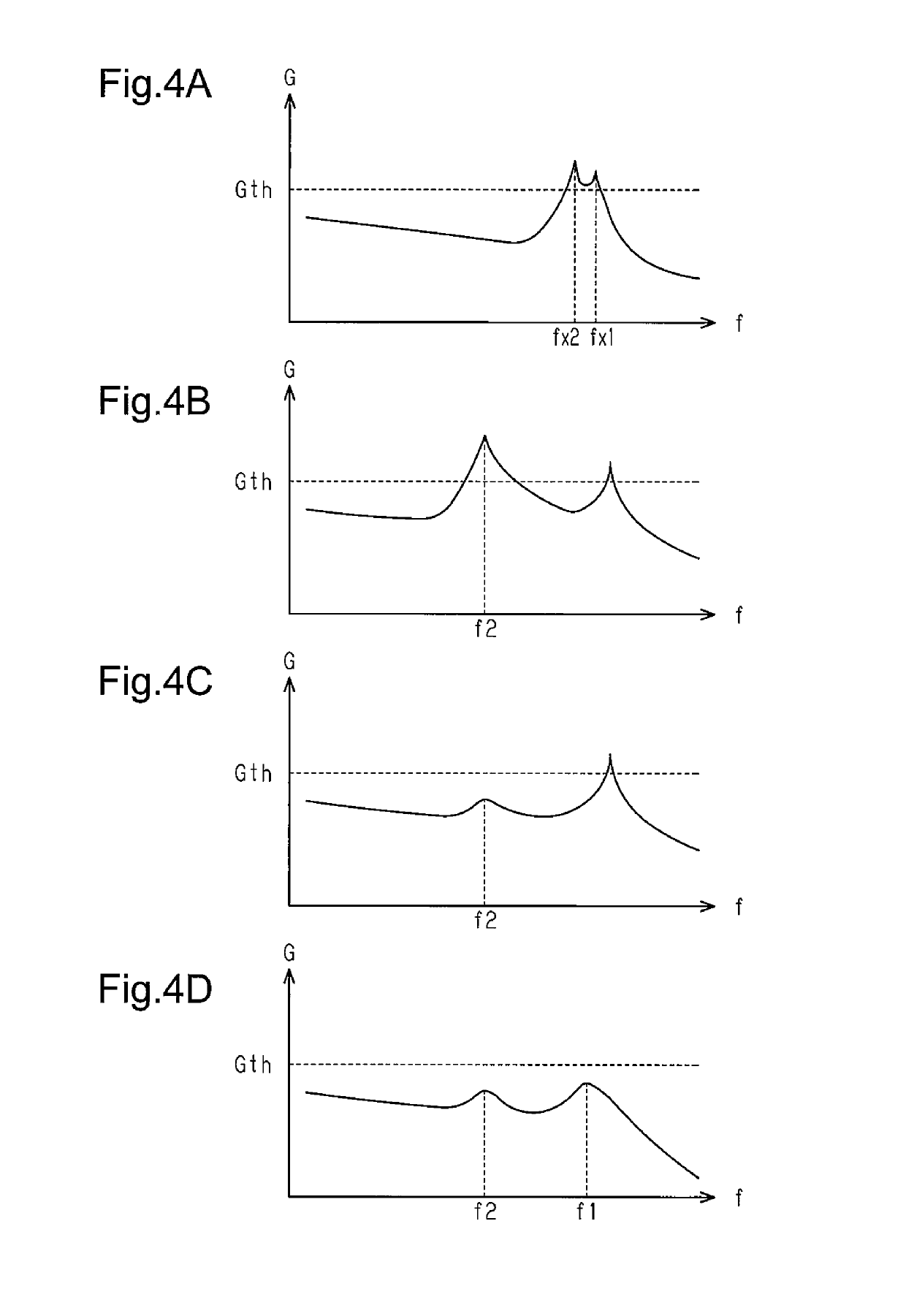
If the frequency band of noise for which leakage is desired to be suppressed is widened to improve the versatility as described above, a resonance frequency may be included in that frequency band, so that leakage of noise at frequencies close to the resonance frequency may not be sufficiently suppressed.

Method used


Image

  • In-vehicle inverter device and in-vehicle fluid machine
  • In-vehicle inverter device and in-vehicle fluid machine
  • In-vehicle inverter device and in-vehicle fluid machine

Examples


Embodiment Construction

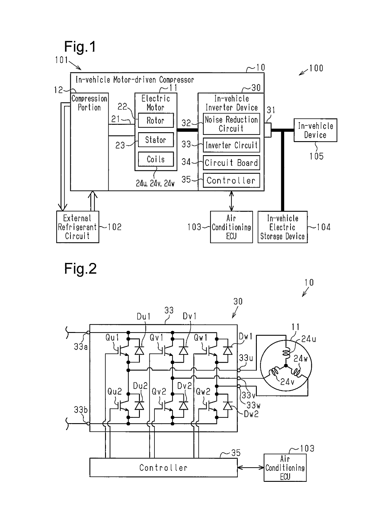
[0018]An in-vehicle inverter device and an in-vehicle fluid machine that accommodates the in-vehicle inverter device according to one embodiment will now be described. In the present embodiment, the in-vehicle fluid machine is an in-vehicle motor-driven compressor that is used in an in-vehicle air conditioner.

[0019]An outline of the in-vehicle air conditioner and the in-vehicle motor-driven compressor will now be described.

[0020]As shown in FIG. 1, a vehicle 100 has an in-vehicle air conditioner 101, which includes an in-vehicle motor-driven compressor 10 and an external refrigerant circuit 102. The external refrigerant circuit 102 supplies refrigerant, which is fluid, to the in-vehicle motor-driven compressor 10. The external refrigerant circuit 102 includes, for example, a heat exchanger and an expansion valve. The in-vehicle motor-driven compressor 10 compresses the refrigerant, and the external refrigerant circuit 102 performs heat exchange of the refrigerant and expands the ref...


PUM


Abstract

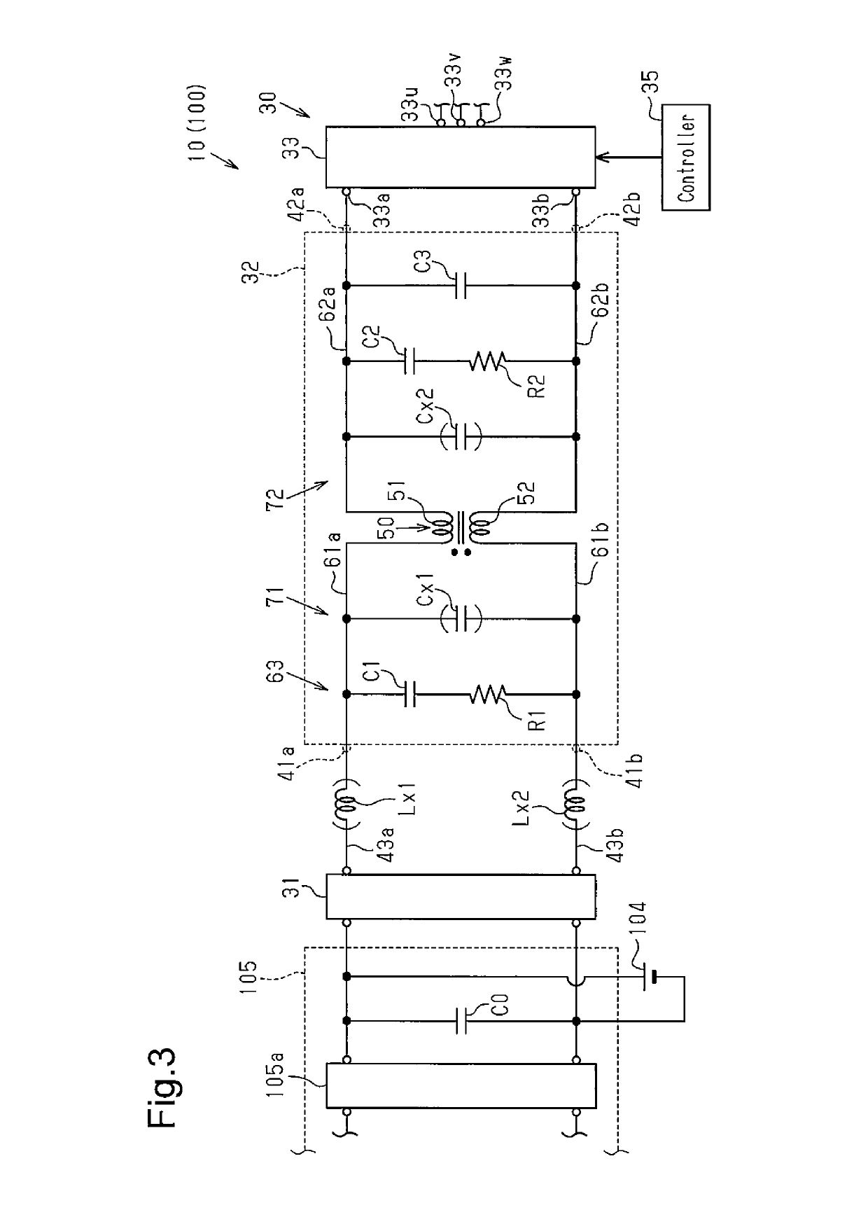
An in-vehicle inverter device includes a noise reduction circuit, which has a common mode choke coil configured to reduce common mode noise and normal mode noise contained in DC power, and an inverter circuit, which receives the DC power in which the noise has been reduced. The noise reduction circuit includes: an input-side capacitor and an input-side resistor provided on the input side of the choke coil; an output-side capacitor and an output-side resistor provided on the output side of the choke coil; a first filter circuit that includes the choke coil, the input-side capacitor, and the input-side resistor; and a second filter circuit that includes the choke coil, the output-side capacitor, and the output-side resistor. The first and the second filter circuits reduce leakage noise generated in the inverter circuit.

Description

BACKGROUND OF THE INVENTION[0001]The present invention relates to an in-vehicle inverter device and an in-vehicle fluid machine.[0002]Japanese Patent No. 5039515 discloses an in-vehicle inverter device that converts DC power into AC power. This in-vehicle inverter device has an inverter circuit having switching elements.[0003]DC power to be converted by an in-vehicle inverter device may be contaminated by both of common mode noise and normal mode noise. In this case, these noises may hinder normal power conversion by the in-vehicle inverter device.[0004]In an inverter circuit, for example, switching actions by switching elements or the like can generate noise. If the noise leaks out of the in-vehicle inverter device, it may adversely affect other in-vehicle devices connected to the in-vehicle inverter device.[0005]In particular, since the specifications of the in-vehicle devices connected to the in-vehicle inverter device differ depending on the type of vehicle, the frequency band o...

Claims


Application Information

Patent Timeline
Patent Type & Authority Patents(United States)
IPC IPC(8): B60L50/50H02P27/08H02M7/44H02K7/14B60H1/32H02M1/14H02M1/12H02M7/5387
CPCH02K7/14B60H1/3222H02M1/14H02M7/44B60L50/50H02P27/08H02M2001/123H02M7/5387F04B49/10H02M7/5395H02P27/085H02M1/123Y02T10/70F04B35/04H02M7/48H02M1/0064
Inventor KAWASAKI, TAKAONAGATA, YOSHIKIKAGAWA, FUMIHIROAMBO, SHUNSUKESUZUKI, KOKI
Owner TOYOTA IND CORP
Learn More