Electrical connector with a multi-part shield

a technology of electrical connectors and shields, applied in the direction of coupling protective earth/shield arrangements, electrical devices, coupling device connections, etc., can solve the problems of leakage of noise in the tube, noise in the wire, etc., and achieve the suppression of outward radiation of noise flowing in the outer conductor, the effect of easy concentration

Active Publication Date: 2021-04-06
SUMITOMO WIRING SYST LTD
View PDF2 Cites 0 Cited by
  • Summary
  • Abstract
  • Description
  • Claims
  • Application Information

AI Technical Summary

Benefits of technology

[0006]The inventors have focused on a tendency of a high-frequency current to flow more near a conductor surface by a skin effect when flowing in a conductor, and arrange the leakage suppressing portion extending toward the wire arrangement area where the wires are arranged. That is, noise generated in the wires can be concentrated on a surface of the leakage suppressing portion extending toward the wire arrangement area and flow from the tube to the shield of the shielded cable through the leakage suppressing portion. In this way, it is possible to suppress the leakage of the noise generated in the wires to outside through the clearance between the first and second covers.
[0008]The leakage suppressing portion extending toward the wire arrangement area is formed on at least one of the first side plate and the second side plate defining the clearance between the first and second covers. That is, noise leaking to outside through the clearance easily can be concentrated on the leakage suppressing portion. In this way, the leakage of the noise to outside through the clearance can be suppressed.
[0010]The present inventors further focused on a tendency of a high-frequency current to be concentrated easily on a corner part formed by two surfaces, out of the skin effect. That is, high-frequency noise in the wires easily is concentrated on the extending end part of the leakage suppressing portion and leakage to outside through the clearance between the first and second covering portions can be suppressed.
[0011]Further, noise flowing in the tube flows on the surface of the tube by the skin effect. Here, the extending end part of the leakage suppressing portion projects inward of the first and second covers. That is, the noise flowing in the tube also can be concentrated on the leakage suppressing portion, i.e. the extending end part (corner part formed by the two surfaces) of the leakage suppressing portion by the skin effect. In this way, outward radiation of noise flowing in the outer conductor also can be suppressed.
[0012]According to this disclosure, it is possible to suppress the leakage of noise to outside.

Problems solved by technology

However, if the barrel is enlarged, clearances may be formed between the lower side plates of the shield shell and the upper side plates of the shield cover, and noise generated in the inner conductors leaks through this clearance between the shield shell and the shield cover.
Further, noise flowing in the tube flows on the surface of the tube by the skin effect.

Method used


Image

  • Electrical connector with a multi-part shield
  • Electrical connector with a multi-part shield
  • Electrical connector with a multi-part shield

Examples


example

[0081]Next, a radiation field strength of this example was obtained and confirmed by calculation.

[0082]The radiation field strength was confirmed for this example and a comparative example.

[0083]The comparative example uses a lower conductor 1 obtained by removing the leakage suppressing portions 58 from the lower conductor 50, as shown in FIGS. 6 and 7.

[0084]That is, the lower conductor 1 of the comparative example is configured such that no leakage suppressing portion is provided on the upper end edges of a pair of linking side plates 2.

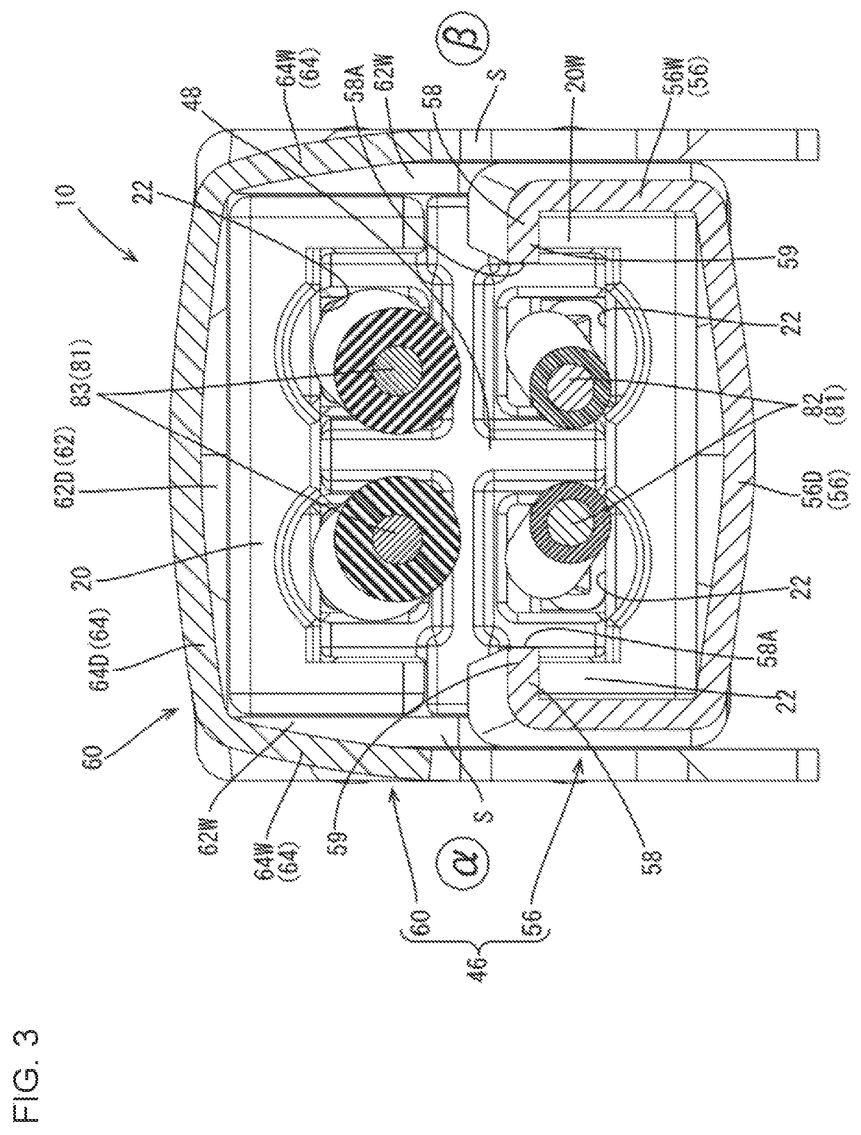
[0085]The radiation field strength was confirmed for the link 46 when noise was generated from the two signal wires in the upper stage. The radiation field strength was confirmed at confirmation positions α, β on both left and right sides of the link 46 in FIG. 3.

[0086]As a result of confirmation, the radiation field strength of this example was lower than that of the comparative example at the both confirmation positions α, β.

[0087]Further, it cou...


PUM


Abstract

A cable with terminals in the present disclosure includes a shielded cable (80) and an outer conductor (40). The shielded cable (80) includes wires (81) and a shield. The outer conductor (40) includes a tube. The tube collectively covers the outer peripheries of the wires (81) exposed from the shield, and includes a first cover and a second cover. The first cover covers the wires from a first side, and the second cover covers the wires from a second side opposite to the first side with clearances (S) defined between the first and second covers. At least one of the first and second covers includes leakage suppressing portions (58). The leakage suppressing portions (58) extend toward a wire arrangement area (48) where the wires (81) are arranged in the tube.

Description

BACKGROUNDField of the Invention[0001]The disclosure relates to a cable with terminals.Related Art[0002]Japanese Unexamined Patent Publication No. 2013-229255 discloses a connector to be mounted on an end part of a shielded cable. This connector includes a shield shell and a shield cover for collectively covering the outer peripheries of inner conductors exposed on the end part of the shielded cable. The shield shell includes a bottom plate, two lower side plates extending up from both sides of the bottom plate and a barrel to be crimped to the shielded cable. The shield cover includes a ceiling plate and two upper side plates extending down from both sides of the ceiling plate. The inner conductors are covered by the bottom plate, the lower side plates, the ceiling plate and the upper side plates by assembling the shield cover with the shield shell from above.[0003]In the shield shell of the connector of this type, the size of the barrel changes according to a diameter of the shiel...

Claims


Application Information

Patent Timeline
Patent Type & Authority Patents(United States)
IPC IPC(8): H01R13/6593H01R13/6592H01R13/648H01R13/6581H01R13/6591H01R9/05
CPCH01R13/6593H01R9/0518H01R13/648H01R13/6485H01R13/6581H01R13/6592H01R13/65912H01R13/65915H01R13/6582H01R13/65914H01R4/184
Inventor KOJIMA, YUSUKE
Owner SUMITOMO WIRING SYST LTD
Why Eureka
Try Eureka