
Fire alarm system

An alarm system, fire technology, applied in the direction of fire alarms, fire alarms that rely on smoke/gas effects, alarms, etc.

Inactive Publication Date: 2010-09-15
PANASONIC CORP
View PDF1 Cites 7 Cited by
  • Summary
  • Abstract
  • Description
  • Claims
  • Application Information

AI Technical Summary

Problems solved by technology

Therefore, it has been impossible to distinguish this change of the sound pressure from the attenuation of the sound pressure depending on the smoke present in the monitoring space, and the system for estimating the smoke density based on the sound pressure of the received sound waves has the problem that , it is impossible to accurately detect the attenuation

Method used


Image

  • Fire alarm system
  • Fire alarm system
  • Fire alarm system

Examples


no. 1 example

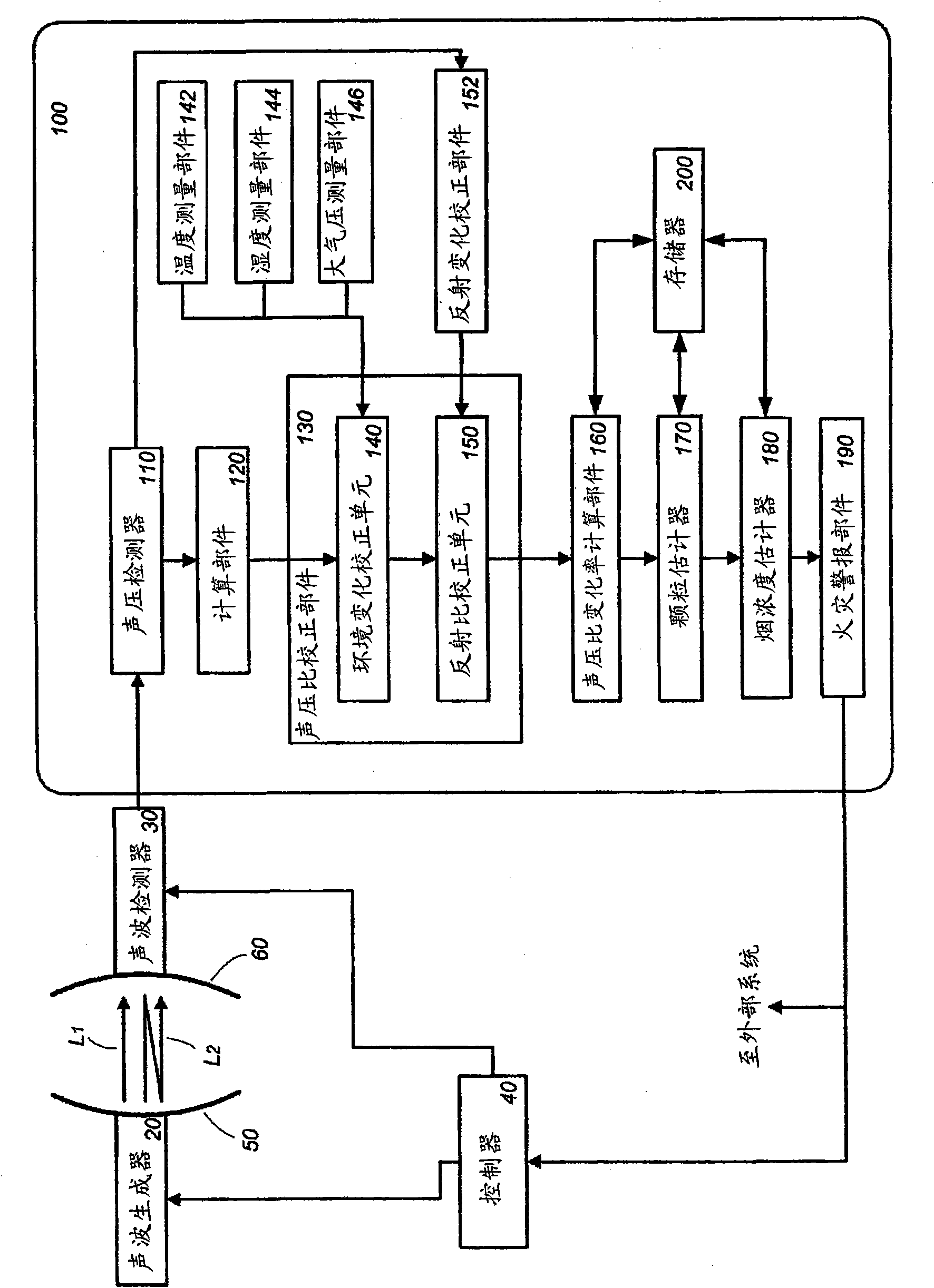
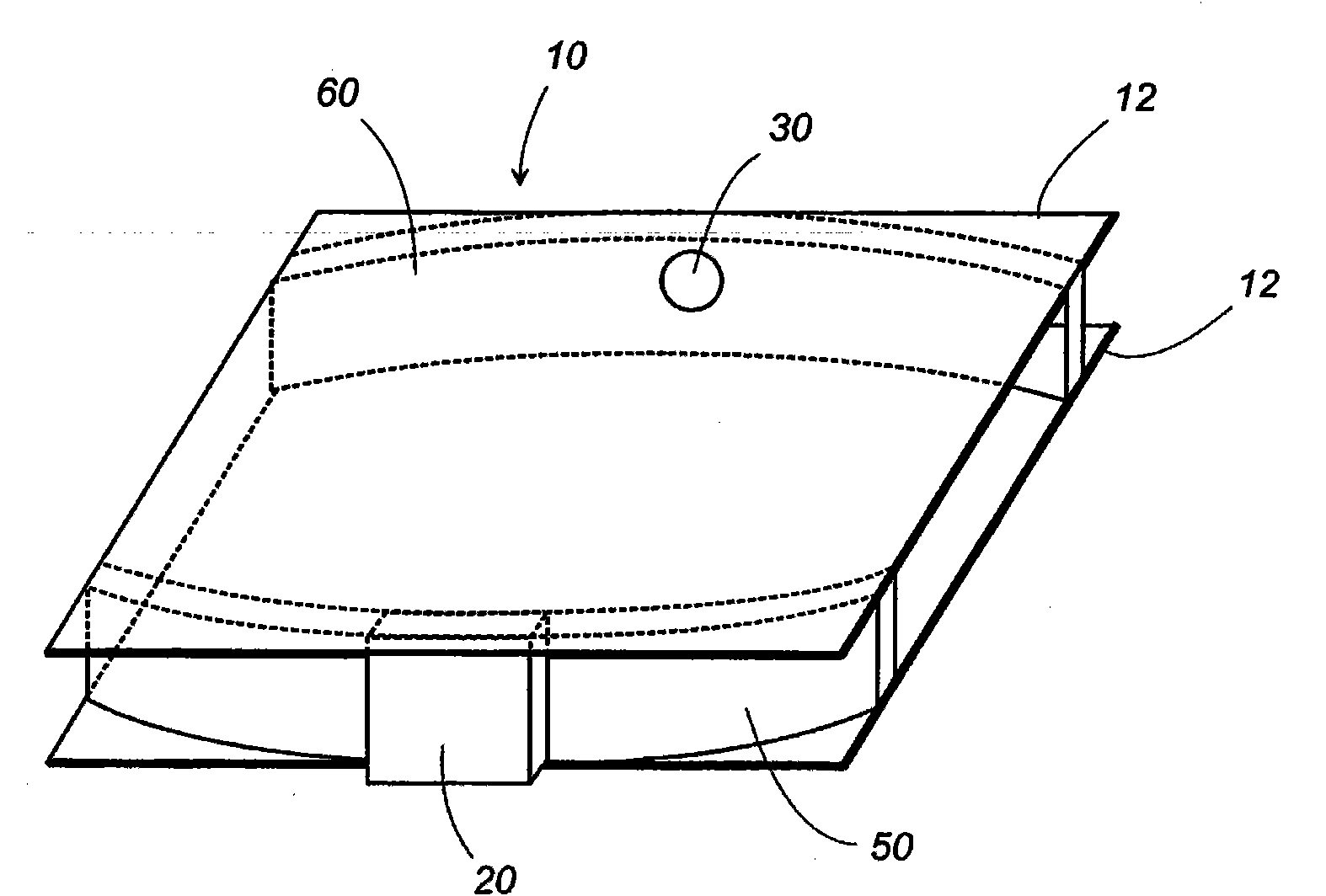
[0042] Such as figure 1 As shown, the fire alarm system according to the first embodiment of the present invention includes a sound wave generator 20 for transmitting ultrasonic waves, a sound wave detector 30 , a controller 40 for controlling the sound wave generator 20 and the sound wave detector 30 , and a processing circuit 100 . The processing circuit 100 processes the output detected by the acoustic wave detector 30, and estimates smoke density and transmits a fire alarm. Fire sensors attached to the interior of the building are then equipped with these generators, detectors, controllers and circuits. The generator and acoustic wave detector comprise a single wave generating element 20 and a single wave receiving element 30, respectively. By combining both elements 20 , 30 with first and second reflectors 50 , 60 the detection unit 10 is composed. The first and second reflectors 50 , 60 are positioned apart from each other by a predetermined distance, and a monitoring ...

no. 2 example

[0123] Figure 15 A fire alarm system according to a second embodiment of the invention is shown. The system differs from the above-mentioned first embodiment in that the wave generating element 20 generates ultrasonic waves containing a plurality of frequency components, and a separation section 220 for separating the plurality of frequency components is formed in the processing circuit 100 . Other configurations and behaviors of the system are basically the same as those of the first embodiment. In the second embodiment, the sound velocity measuring part 145 is used, and the system is configured to calculate the humidity of the monitored space.

[0124] In order to transmit ultrasonic waves including a plurality of frequency components from the wave generating element 20 as an acoustic wave generator, the controller 40 of the second embodiment supplies the wave generating element 20 with a driving input waveform as a half-sine solitary wave. Such as Figure 16A As shown, ...


PUM

PropertyMeasurementUnit
porosityaaaaaaaaaa
porosityaaaaaaaaaa

Abstract

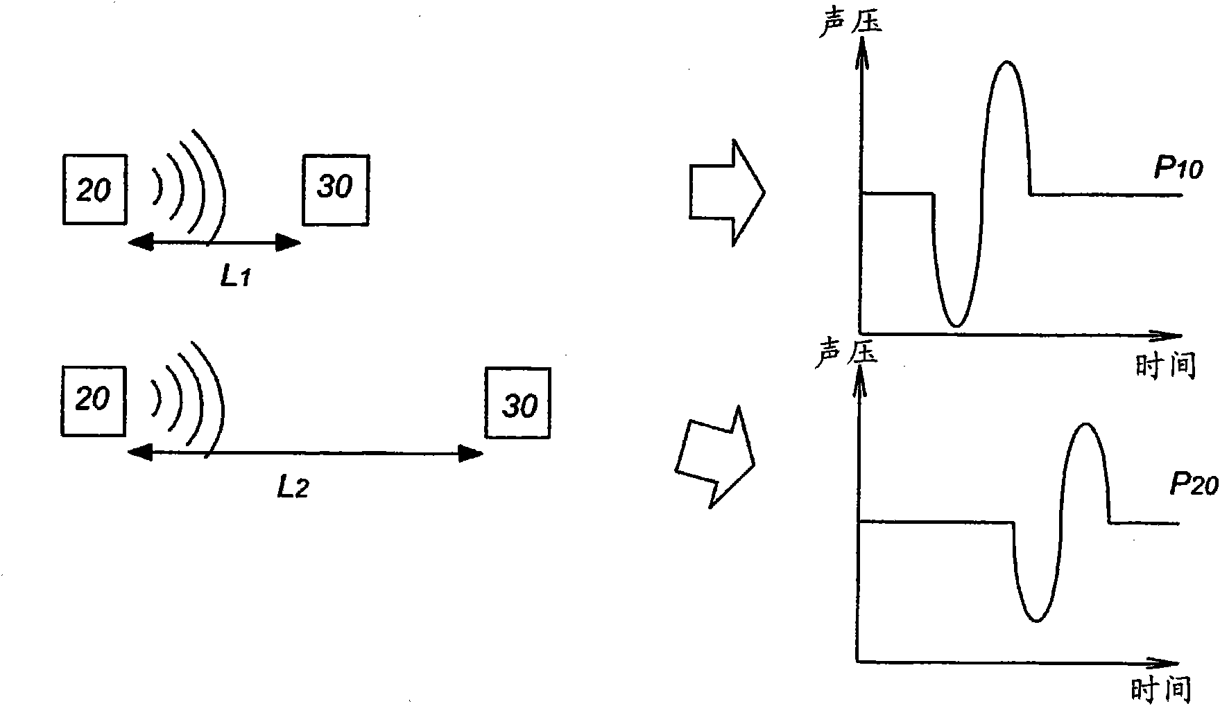
In a fire alarm system for judging the occurrence of a fire by ultrasound, a sound wave generating means and a sound wave detecting means are disposed so as to detect sound waves traveling through two propagation paths with different path lengths. The system comprises a sound pressure ratio calculating means for calculating a sound pressure ratio that is the ratio between a first detected sound pressure that is the sound pressure of the sound wave propagating through the first propagation path and a second detected sound pressure that is the sound pressure of the sound wave propagating through the second propagation path and a smoke density estimating means. The smoke density estimating means obtains the rate of change between the sound pressure ratio calculated by the sound pressure ratio calculating means and a predetermined standard sound pressure ratio and determines the smoke density from the rate of change in accordance with a preset relational expression representing the relation between the rate of change and the smoke density. The fire is judged to have occurred when the smoke density exceeds a predetermined threshold value.

Description

technical field [0001] The present invention generally relates to a fire alarm system, and more particularly, to a fire alarm system that estimates smoke density in a monitored space by using sound waves, and determines the presence or absence of a fire based on the smoke density. Background technique [0002] Japanese Patent Application Publication No. 2005-258747 discloses a fire alarm system using sound waves. This system estimates the density of smoke existing in the monitoring space and the temperature of the monitoring space, based on fluctuations in sound pressure when sound waves emitted from a sound source are received through the monitoring space, and fluctuations until the time when the sound waves are received , to determine the presence or absence of a fire. [0003] However, the received sound pressure undergoes many changes due to changes over time of sensors for receiving sound waves, and characteristic changes depending on temperature and humidity. Therefo...

Claims


Application Information

Patent Timeline
Patent Type & Authority Applications(China)
IPC IPC(8): G08B17/10G01N29/00G01N29/02
CPCG01N2291/0217G08B29/24G01N2291/045G01N2291/048G01N29/4427G01N29/032G01N29/348G08B13/1968G08B17/10G08B17/00G08B17/113
Inventor 渡部祥文本多由明林雅则高田裕司西川尚之
Owner PANASONIC CORP
Learn More