Unidirectional load self-braking spiral braking device

一种螺旋式、制动器的技术,应用在卷扬装置等方向,能够解决发热量大、使用寿命和制动可靠性不是很理想、散热困难等问题

Active Publication Date: 2010-09-22
ZHEJIANG NOWVOW MECHANICAL & ELECTRICAL
View PDF0 Cites 6 Cited by
  • Summary
  • Abstract
  • Description
  • Claims
  • Application Information

AI Technical Summary

Problems solved by technology

When the winch is working, it is necessary to use brakes to ensure that the heavy objects pulled will not slide down when the motor stops or is damaged. There are many types of brakes used in existing winches, including cone drum type, expanding ring type and ratchet type, each of which has its own advantages and disadvantages. Features, but the service life of the expanding coil winch is short, and the ordinary ratchet winch is easy to drop the rope and drop objects. The application of the cone drum type on the winch is better than the other two brakes in terms of the working performance of the winch and its own service life. However, it is not very ideal in terms of long-term service life and braking reliability.
Moreover, the above three types of brakes also have a common disadvantage, that is, they generate a lot of heat during work, and it is difficult to dissipate heat, which accelerates the damage of the winch.
Therefore we are sternly aware that in order to ensure the safety of field driving, the winch in the prior art is still difficult to be reassuring, and it is necessary to invent a brake that can overcome the above-mentioned shortcomings and can better satisfy the working performance of the winch. brake

Method used


Image

  • Unidirectional load self-braking spiral braking device
  • Unidirectional load self-braking spiral braking device
  • Unidirectional load self-braking spiral braking device

Examples


Embodiment Construction

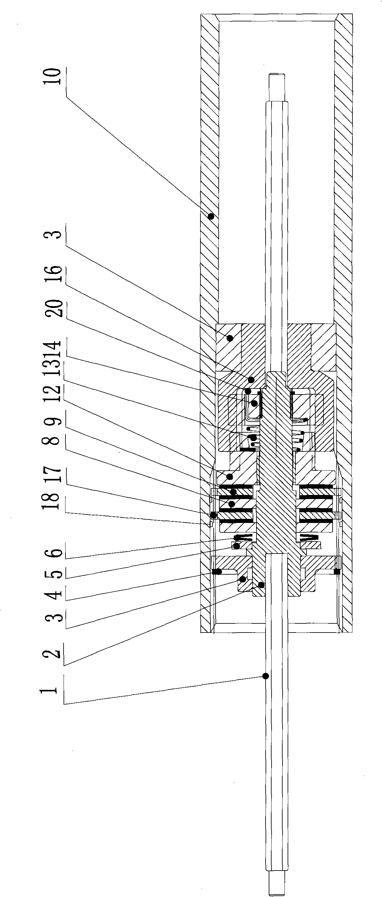
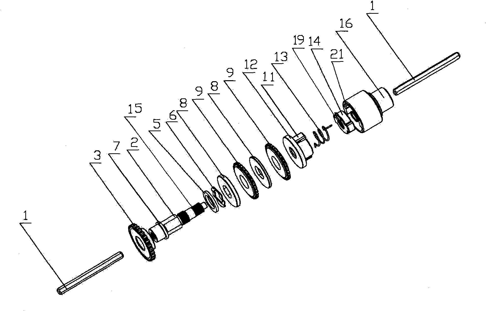
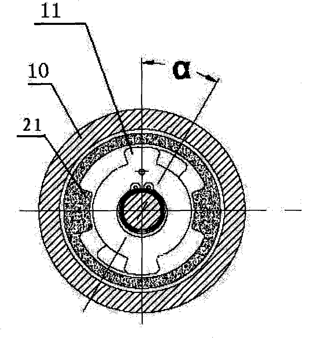
[0018] Such as figure 1 , figure 2 as well as image 3 As shown, a self-made spiral brake with one-way load of the present invention includes a reel 10, two bearing housings 3 are installed in the reel 10, a brake shaft 2 is erected between the two bearing housings 3, and the two ends of the brake shaft 2 are connected There is a transmission shaft 1, and the front end of the brake shaft 2 is provided with a fixing piece 7, starting from the fixing piece 7, the inner friction plate 8 and the outer friction plate 9 which are installed alternately on the brake shaft 2, and the internal thread pressure plate 12, Torsion spring 13, connecting piece 14, brake coupling 16, the inner friction plate 8 meshes with the brake shaft 2, the outer ring of the outer friction plate 9 has external teeth 17, and the front end sleeve of the brake coupling 16 Connected to the outside of the internally threaded pressure plate 12, the torsion spring 13 and the connecting piece 14, the reel 10 is...


PUM


Abstract

The invention aims at providing a unidirectional load self-braking spiral braking device, which has the advantages of fast braking respondence, good effect, good heat radiation, capability of ensuring the braking reliability and long service life. In order to reach the effect, the unidirectional load self-braking spiral braking device comprises a braking shaft, transmission shafts are connected at both ends of the braking shaft, the front end of the braking shaft is provided with a fixed element, from the fixed element, an inner friction sheet, an outer friction sheet, an internal threaded press plate torsional spring, a connecting sheet and a braking shaft coupling are sequentially sheathed on the braking shaft, wherein the inner friction sheet and the outer friction sheet are in alternative arrangement, the inner friction sheet and the braking shaft are engaged, outer teeth are arranged on the outer ring of the outer friction sheet, and inner teeth matched with the outer teeth of the outer ring of the outer friction sheet are also arranged in a wound roll. Because of the adoption of the structure, the unidirectional load self-braking spiral braking device of the invention overcomes the problems of heat radiation and the like of cone drum type, expansion ring type and ratchet wheel braking devices in the prior art in a fire-new braking mode, and the invention is particularly suitable for being used on electric hoisting winches.

Description

technical field [0001] The invention relates to a braking device, in particular to a self-made spiral brake with one-way load for winch braking. Background technique [0002] More and more urbanites like to go for a ride in the wild by themselves. If they encounter harsh natural environments, they may get the car into an unfavorable situation and it is difficult to get out. At this time, a winch is needed to help the vehicle get out of trouble. When the winch is working, it is necessary to use brakes to ensure that the heavy objects pulled will not slide down when the motor stops or is damaged. There are many types of brakes used in existing winches, including cone drum type, expanding ring type and ratchet type, each of which has its own advantages and disadvantages. Features, but the service life of the expanding coil winch is short, and the ordinary ratchet winch is easy to drop the rope and drop objects. The application of the cone drum type on the winch is better than t...

Claims


Application Information

Patent Timeline
Patent Type & Authority Applications(China)
IPC IPC(8): B66D5/14
CPCB66D5/12
Inventor 张国纲王明强丁国强
Owner ZHEJIANG NOWVOW MECHANICAL & ELECTRICAL
Why Eureka
Try Eureka