Pivoting device

A technology of pivoting and accommodating grooves, which is applied in the field of pivoting devices, can solve problems such as inconvenient use, and achieve the effect of easy operation

Active Publication Date: 2010-09-22
PEGATRON
View PDF0 Cites 10 Cited by
  • Summary
  • Abstract
  • Description
  • Claims
  • Application Information

AI Technical Summary

Problems solved by technology

In this way, every time an adjustment is made, the above-mentione

Method used


Image

  • Pivoting device
  • Pivoting device
  • Pivoting device

Examples


Example Embodiment

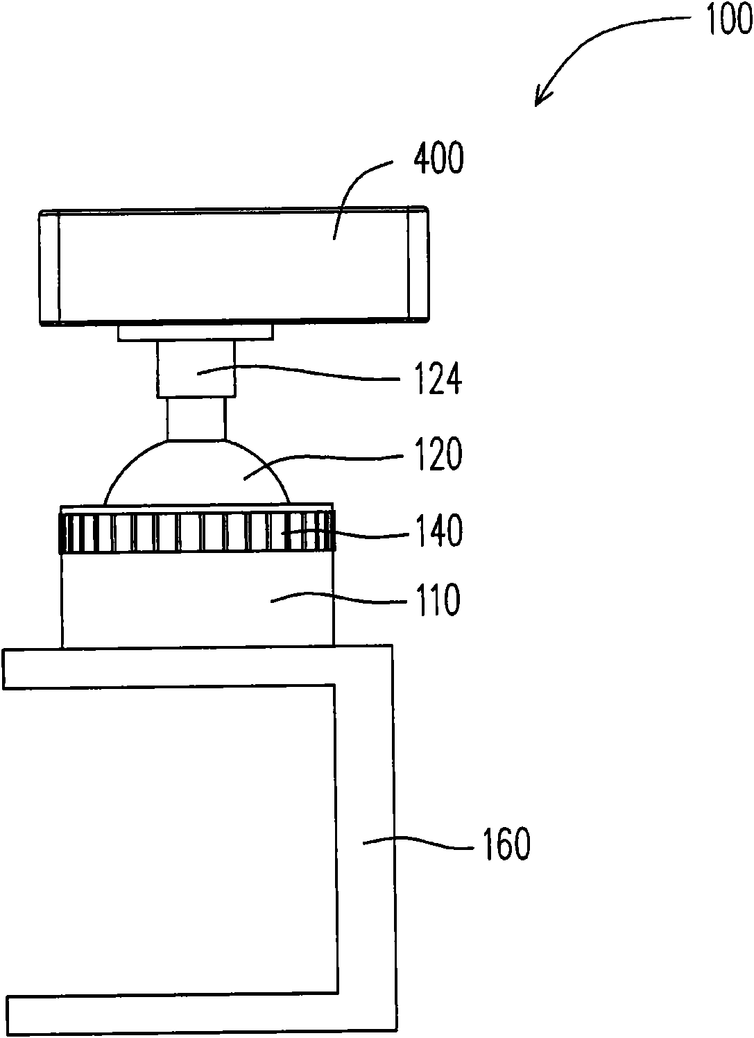
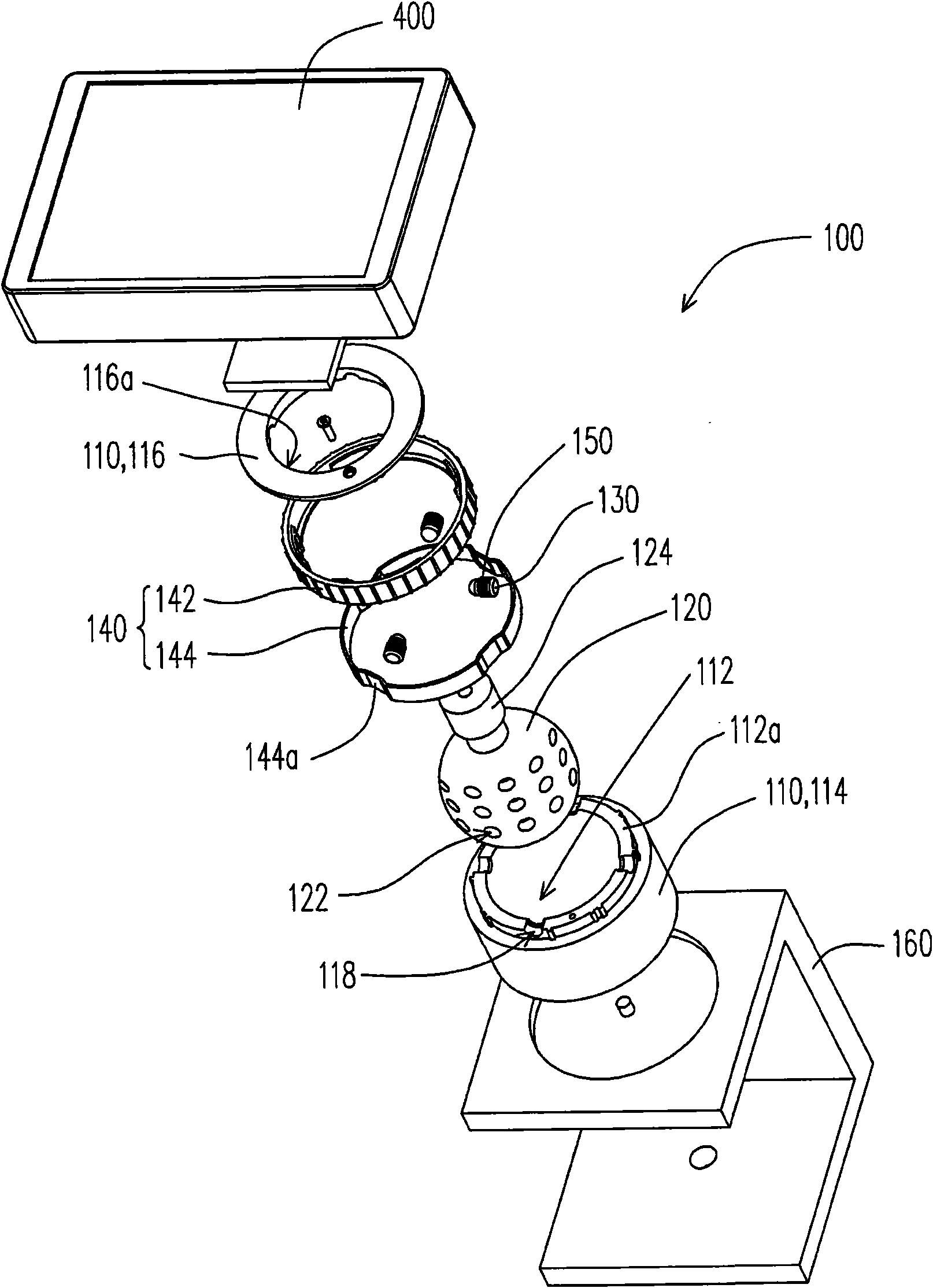
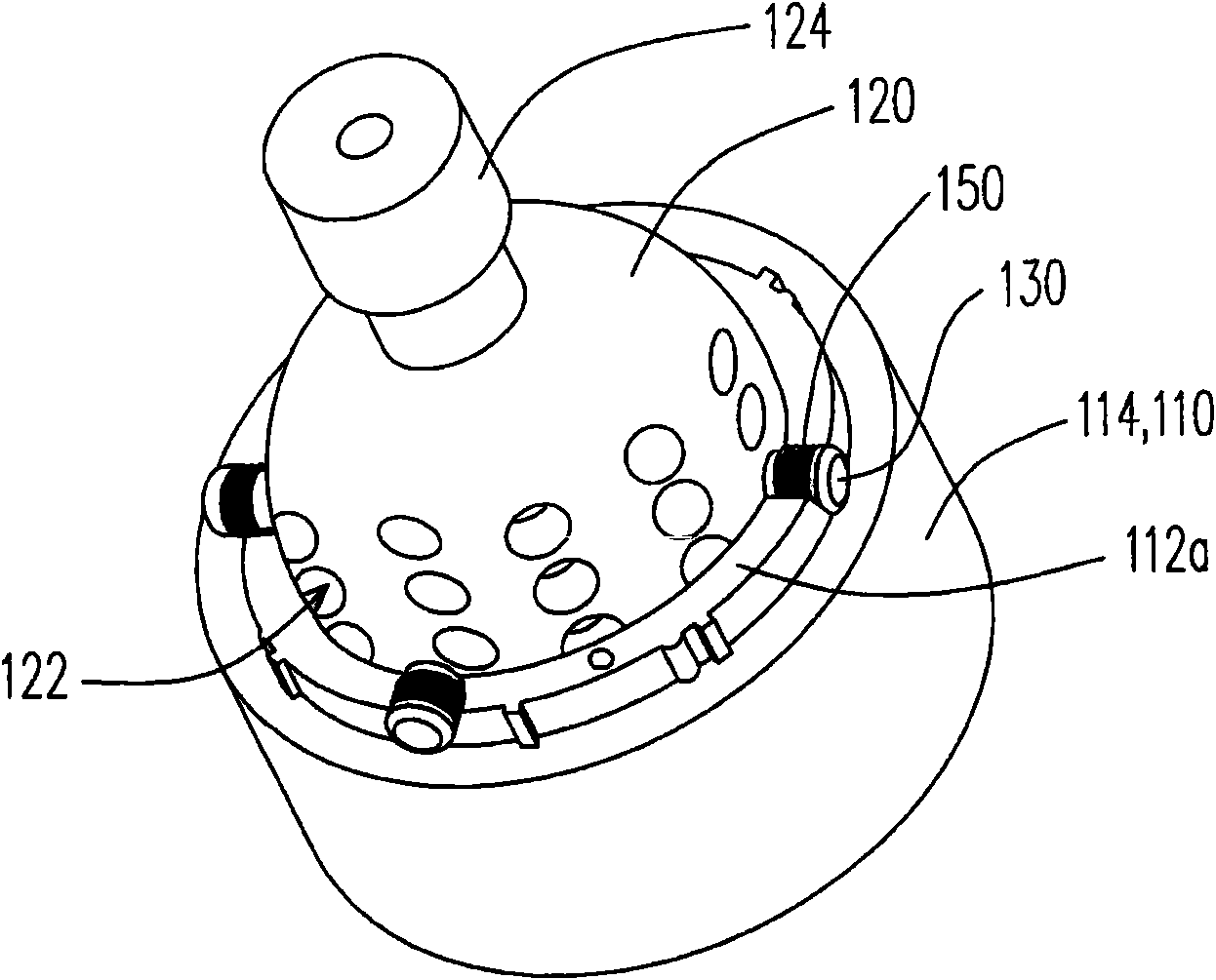
[0025] figure 1 It is a side view of the pivoting device according to an embodiment of the present invention. figure 2 for figure 1 An exploded view of the transfer device. Figure 3 to Figure 5 for figure 1 Partial structural perspective view of the pivoting device. Please refer to Figure 1 to Figure 5 , the pivoting device 100 of this embodiment includes a bearing housing 110 , a ball joint 120 , a plurality of positioning pins 130 (four are shown) and a limiting ring 140 . The bearing seat 110 has a receiving groove 112 . The ball joint 120 is disposed in the receiving groove 112 , and the surface of the ball joint 120 has a plurality of positioning holes 122 .

[0026] The positioning pin 130 is arranged on the bearing seat 110 and partially protrudes from the inner wall of the receiving groove 112, and the positioning pin 130 is set to slide toward or away from the ball joint 120, and after the bearing seat 110 and the ball joint 120 are rotated to a specific posi...


PUM


Abstract

The invention relates to a pivoting device, which comprises a bearing carrier, a ball joint, a plurality of locating pins and a spacing ring, wherein the bearing carrier is provided with a containing groove; the ball joint is arranged in the accommodation groove; the surface of the ball joint is provided with a plurality of locating holes; the locating pins are arranged on the bearing carrier and can slide towards or away from the ball joint; when the bearing carrier and the ball joint relatively rotate to a specific position, the locating pins are respectively corresponding to part of the locating holes; the spacing ring is arranged along the opening of the accommodation groove and around the locating pins; and when the bearing carrier and the joint relatively rotate to specific position, the spacing ring abuts against the locating pins, so that the locating pins are clamped in the corresponding locating holes.

Description

technical field [0001] The present invention relates to a pivoting device, and in particular to a pivoting device having a ball joint. Background technique [0002] Due to the continuous advancement of information technology, various electronic products have come out one after another, such as Personal Digital Assistant (PDA), Tablet PC (Tablet PC), digital camera and Global Positioning System (Global Positioning System, GPS) device etc. The above-mentioned electronic device can be further connected to the pivoting device according to the needs of use. For example, the pivoting device in the car can be used to mount objects such as a global positioning system device or a personal digital assistant to facilitate viewing and operation of the user. In addition, objects such as digital cameras and tablet computers can also be mounted on the pivoting device for convenience. [0003] Generally speaking, the above-mentioned objects mounted on the pivoting device can be rotated r...

Claims


Application Information

Patent Timeline
IPC IPC(8): F16C11/06F16C11/10
Inventor 蔡佳明马绍棠陶奕蓁李柏纬蔡汪幸
Owner PEGATRON
Why Eureka
Try Eureka