Assembled bulletproof flashboards

A bullet-proof plug-in, assembled technology, which is applied to defenses, defense devices, protective equipment, etc., can solve the problems of the inability to realize the structure of the bullet-proof plug-in, and achieve the effects of increased cost, rapid disassembly and assembly, and good integrity.

Active Publication Date: 2010-09-22
SHENYANG JIHUA 3547 SPECIAL TYPE ARMAMENT
View PDF6 Cites 11 Cited by
  • Summary
  • Abstract
  • Description
  • Claims
  • Application Information

AI Technical Summary

Problems solved by technology

[0003] The present invention solves the bullet-proof inserts issued by individual soldiers in the prior art. In actual combat, when there is no bunker available in an open area or firepower from a high point of the enemy or other emergencies need to quickly organize a larger bunker, the current The technical problem that the structure of the bulletproof board cannot be realized provides an assembled bulletproof board, which includes a main body of the bulletproof board, and socket joints are distributed on the periphery of the main body of the bulletproof board, and each of the socket joints One end is fixed on the main body of the bulletproof plugboard, and the other end with the socket extends out of the main body of the bulletproof plugboard; the distance between two adjacent socket joints on the plugboard is not less than the width of the socket joint, and the socket on the plugboard The location of each socket fitting on opposite sides is staggered

Method used


Image

  • Assembled bulletproof flashboards
  • Assembled bulletproof flashboards
  • Assembled bulletproof flashboards

Examples


Embodiment

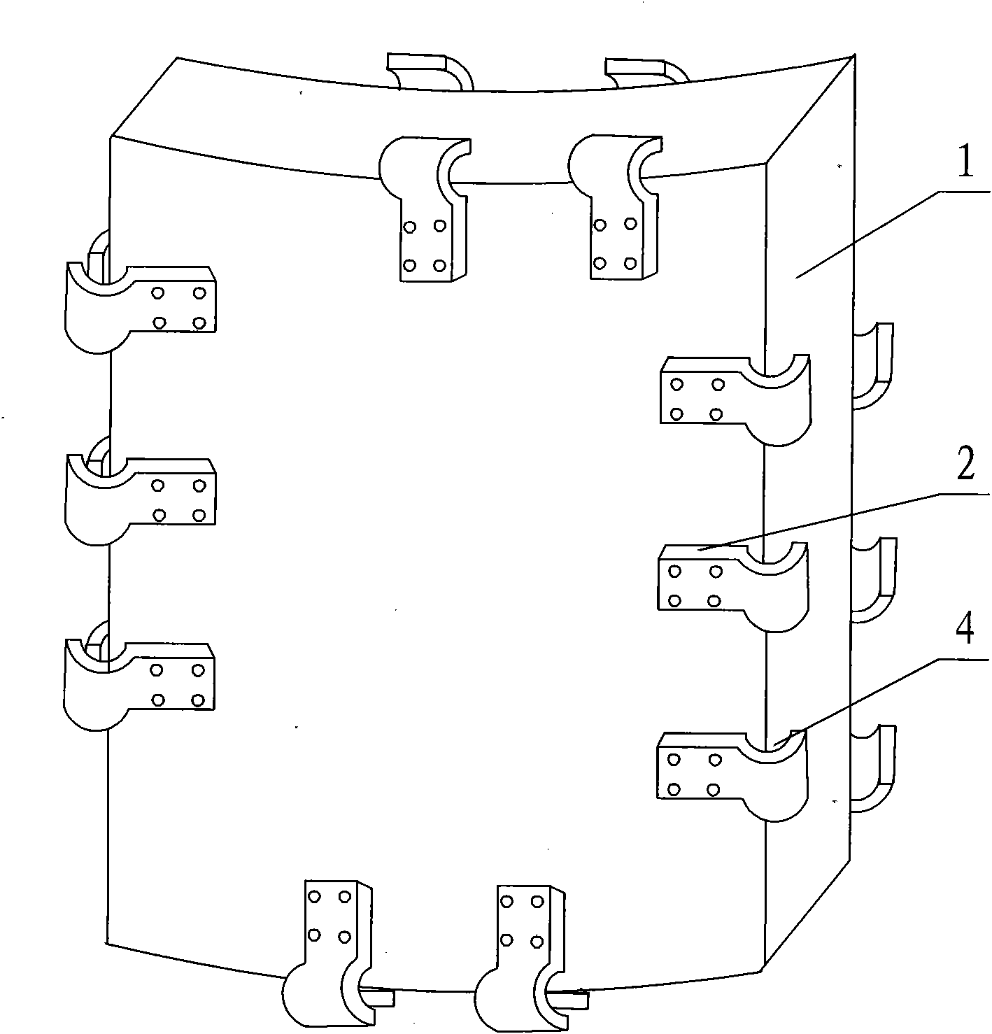
[0023] see figure 1 , there are socket joints 2 distributed on the periphery of the front and back sides of the main body of the bulletproof board 1, one end of each socket joint 2 is fixed on the main body 1 of the bulletproof board, and the other end with the socket 4 extends to the bulletproof board The main body 1 is outside the body; the distance between two adjacent socket joints 2 fixed on the plugboard is not less than the width of the socket joint 2, and the relative positions of each socket joint 2 on the opposite sides of the plugboard are staggered, It is convenient to connect with another board. Each bulletproof plate main body 1 and the socket joint 2 thereon can be assembled and formed by bolts, or can be formed as a whole by one-time casting of a mold. The main body 1 of the plugboard is made of UHMWPE and aramid fiber, and the socket joint 2 is made of reinforced PA.

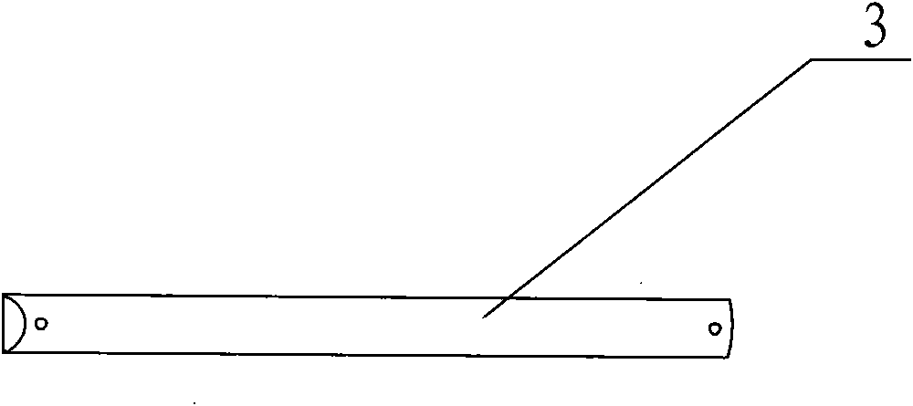
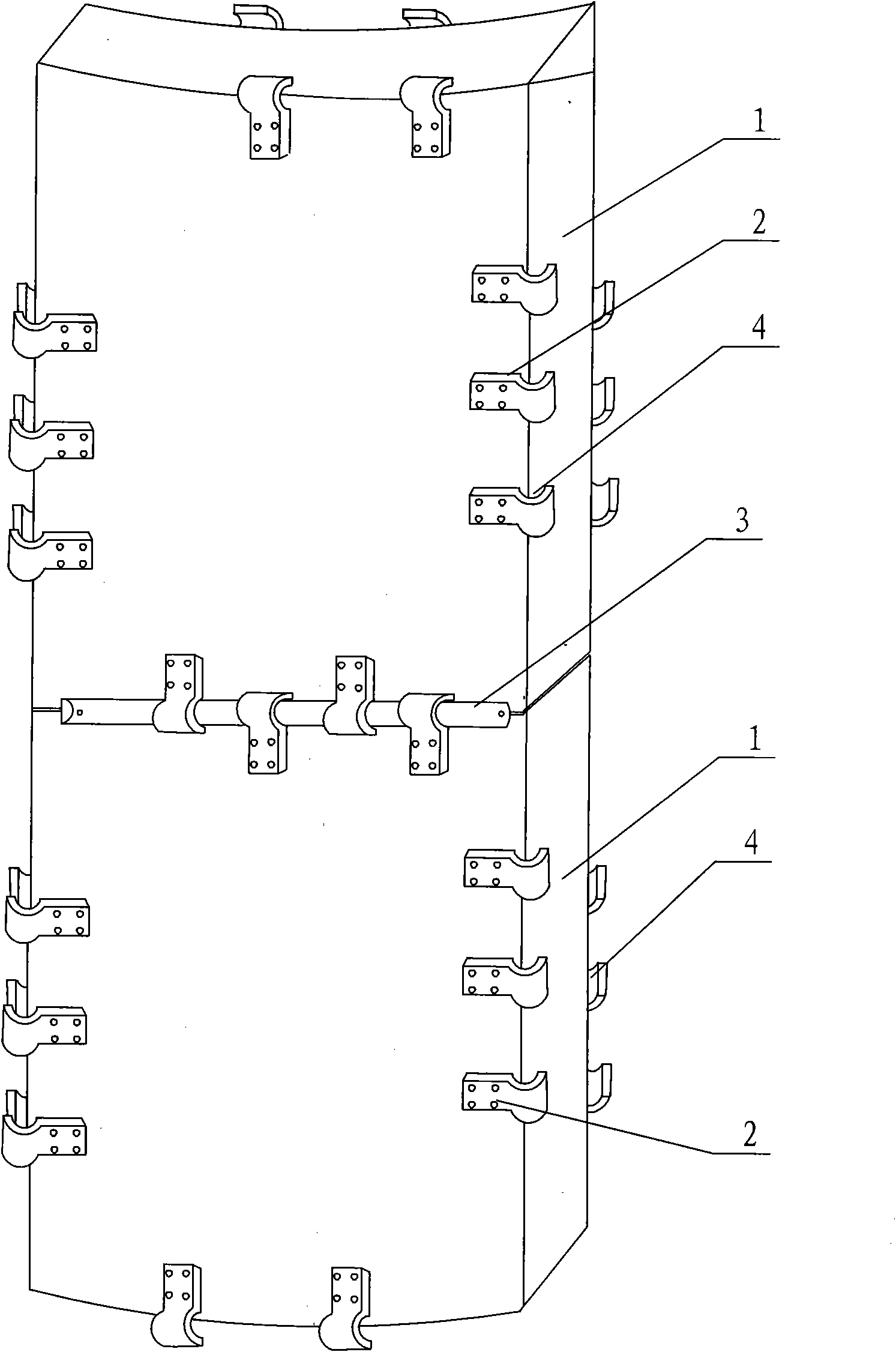
[0024] see figure 2 , image 3 , Figure 4 , according to actual combat needs, through...


PUM


Abstract

The invention relates to assembled bulletproof flashboards, and aims to solve the technical problem that a structure of the conventional bulletproof flashboards allocated to a single soldier cannot be realized when large blindage needs to be organized quickly due to emergencies such as open terrains, no available blindage and the like in the process of actual combat. The assembled bulletproof flashboards comprise a bulletproof flashboard main body, wherein a group of bell and spigot joints are distributed at the periphery of two surfaces of the bulletproof flashboard main body; one end of each bell and spigot joint is fixed on the bulletproof flashboard main body, and the other end with a faucet extends out of the bulletproof flashboard main body; the distance between the two adjacent bell and spigot joints on the flashboards is more than or equal to the width of each bell and spigot joint; and opposite positions of the bell and spigot joints on two opposite sides of the flashboards are arranged in a staggered mode. Through the bell and spigot joints on the bulletproof flashboard main body, two sides with the same side length on at least two flashboards are subjected to butt joint in the staggered mode through the faucets, and the faucets which are subjected to the butt joint in the staggered mode are subjected to plug assembly through bulletproof seam strips to form bulletproof shields or bulletproof walls. The assembled bulletproof flashboards have the advantages of convenience, flexibility, quick assembly and disassembly and capability of dealing with various possible situations in time during actual combat and greatly reducing the casualty rate.

Description

Technical field: [0001] The invention relates to bulletproof equipment, in particular to an assembled bulletproof board. It is not only suitable for the army and the armed police to use bulletproof plates as individual protective equipment during missions or operations, but also suitable for use as bulletproof shields and bulletproof walls after the bulletproof plates are assembled. Background technique: [0002] At present, the bulletproof inserts distributed by individual soldiers are used as the fatal parts of the front and rear chests of individual soldiers. In actual combat, it is found that in the following situations, due to poor prevention, great casualties will be caused. For example, when there is no shelter available in an open area or around an alley, when the firepower in front is dense and cannot be suppressed by our side, or when there is firepower from a high point of the enemy or there is dense firepower indoors, but it is necessary to rush into the room; an...

Claims


Application Information

Patent Timeline
Patent Type & Authority Applications(China)
IPC IPC(8): F41H1/00F41H5/08F41H11/00
Inventor 韩同毅佟胜利傅树深
Owner SHENYANG JIHUA 3547 SPECIAL TYPE ARMAMENT
Why Eureka
Try Eureka