Hairspring supporting structure, hairspring balance wheel structure and mechanical clock

A technology of supporting structure and hairspring, which is applied to mechanically driven clocks, clocks, clock driving mechanisms, etc., can solve the problem that the spring structure is not easy to realize, etc.

Inactive Publication Date: 2010-09-22
SEIKO INSTR INC
View PDF5 Cites 16 Cited by
  • Summary
  • Abstract
  • Description
  • Claims
  • Application Information

AI Technical Summary

Problems solved by technology

[0006] However, in a small mechanical timepiece such as a wristwatch (wristwatch), it is not easy to implement a spring structure like the one proposed in the hairspring stud, so it is not very realistic.

Method used


Image

  • Hairspring supporting structure, hairspring balance wheel structure and mechanical clock
  • Hairspring supporting structure, hairspring balance wheel structure and mechanical clock
  • Hairspring supporting structure, hairspring balance wheel structure and mechanical clock

Examples


Embodiment

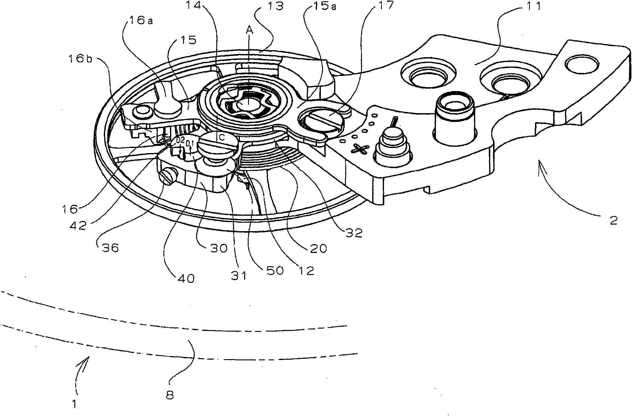
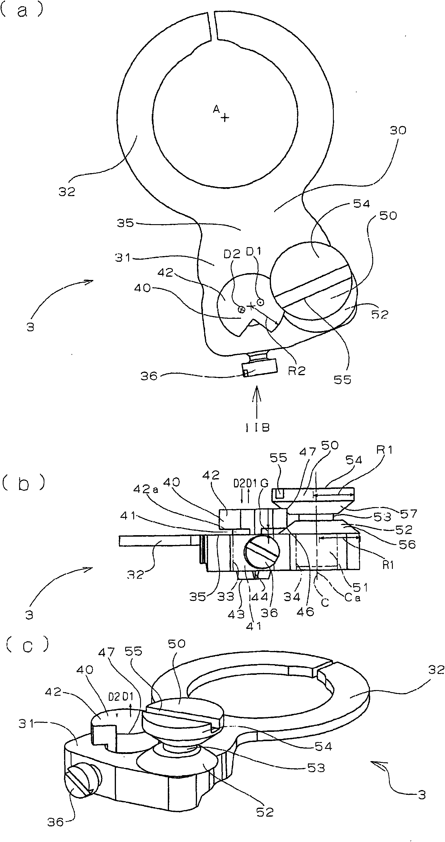
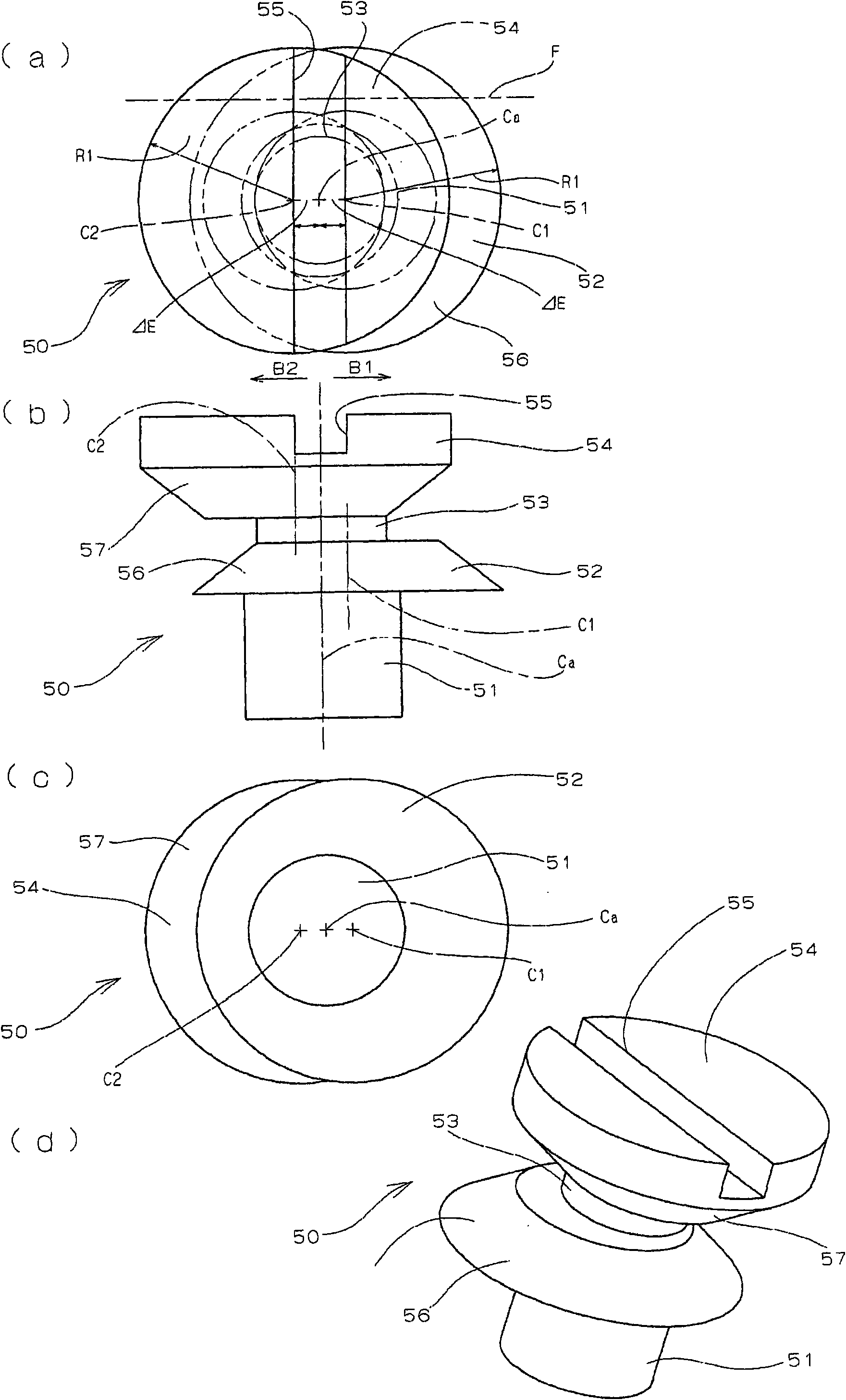
[0031] exist figure 1 shows a hairspring balance structure 2, which is mounted on a supporting substrate such as a main board (not shown) through a hairspring balance bridge 11 in the case 8 of the mechanical wristwatch 1, and figure 2 The hairspring supporting structure 3 is shown in , and the hairspring supporting structure 3 includes a hairspring stud ring 30 , a hairspring stud 40 and a hairspring stud height adjustment pin 50 .

[0032] The hairspring balance wheel structure 2 has a balance wheel 13 fixed to the balance shaft 12 and a hairspring 20 in the form of a spiral spring. The inner peripheral end of the hairspring 20 is fixed to a hairspring collet (not shown) which is fixed to the balance spring collet. The shaft 12 and the outer peripheral ends of the balance spring 20 are fixed to the balance spring stud 40 , and the balance spring stud 40 is supported by the balance spring stud ring 30 . The balance spring 20 is engaged with the adjustment pin 16 supported b...


PUM


Abstract

The present invention provides a hairspring supporting structure which can adjust the offset of the hairspring from a plane to a lowest limit, a hairspring balance wheel structure and a mechanical clock. The hairspring supporting structure of mechanical clock comprises a hairspring stud height position adjusting mechanism which shifts the hairspring stud in a vertical direction relatively to a hairspring stud ring. The hairspring stud is provided with a shaft which is inserted and penetrates the hairspring stud ring and a disc-shaped flange. The hairspring stud height position adjusting mechanism is provided with a hairspring stud height position adjustor which comprises the following components: an adjusting shaft which is matched with the hairspring stud ring; and an adjustor body which is provided with a reference frustum-shaped surface which is eccentric relatively the adjusting shaft at one side of the adjusting shaft. When the hairspring stud height position adjustor rotates along a central axis of the adjusting shaft, the adjustor body presses one end edge of the disc-shaped flange of the hairspring stud thereby shifting the hairspring stud upwards or downwards relatively to the hairspring stud ring.

Description

technical field [0001] The present invention relates to a hairspring support structure of a mechanical timepiece, and more specifically, to a hairspring support structure, a hairspring balance structure with the support structure, and a mechanical timepiece with the structure. [0002] In addition, in this specification, the extension direction of a balance shaft is called an up-down direction or a height direction. In addition, hereinafter, as usual, the side where the upper bearing of the balance with hairspring is located is referred to as upper (upper), and the side where the lower bearing of the balance with hairspring is located is referred to as lower (lower). Background technique [0003] In mechanical timepieces, usually, the outer peripheral end of the spiral hairspring is fixed to the hairspring stud. The hairspring stud is pressed into the hairspring stud through-hole of the hairspring stud ring for fitted fitting, or is inserted into the through-hole and fixed ...

Claims


Application Information

Patent Timeline
Patent Type & Authority Applications(China)
IPC IPC(8): G04B1/14G04B17/06
CPCG04B17/325G04B18/023
Inventor 荒川康弘
Owner SEIKO INSTR INC
Why Eureka
Try Eureka