Particle impactor with selective height adjustment

a technology of height adjustment and particle impactor, which is applied in the field of particle sampling, collection and analysis, can solve the problems of pharmaceutical products at risk of failing to meet the cleanliness level standards, real-time efficiency, and fabrication efficiency reduction

Active Publication Date: 2018-02-06
PARTICLE MEASURING SYST
View PDF20 Cites 18 Cited by
  • Summary
  • Abstract
  • Description
  • Claims
  • Application Information

AI Technical Summary

Benefits of technology

[0010]In an embodiment, provided herein are impactors having a continuously adjustable separation distance between an impactor surface and the exit of an air inlet that is opposibly positioned to the impactor surface so as to facilitate positioning of the impact surface at an optimal separation distance from the exit of the air inlet. This provides a number of functional benefits, including being able to use an impactor with a wide range of biological growth media and containers, wherein change in the depth of the biological growth media is accommodated herein by the adjustable separation distance. Containers and corresponding growth media that may be deeper or higher may be accommodated as well as relatively thinner containers and corresponding growth media to achieve an optimal separation distance irrespective of the container and growth media depth.
[0012]Another advantageous aspect of the devices and methods provided herein is the ability to easily and reliably step through the separation distances in an indexed or ratcheting-type manner. For example, while the separation distances are continuously adjustable, it is helpful to a user to have some indication as to the increment by which the separation distance changes. Any of the impactors and methods provided herein may provide an indication of such step change in separation distance by a separation distance step indicator operably connected to the base plate or the adjustment plate to indicate a change in the separation distance for a given rotation of the adjustment plate. The invention is compatible with a wide range of components to facilitate such changes, including a paired protrusion element and indent that provide reliable, but reversible, setting of a separation distance.
[0019]Any of the impactors provided herein may further comprising a protrusion element connected to the base plate and a plurality of indents formed on a surface of the adjustment plate, wherein the protrusion element is configured to mate with each of the plurality of indents. This may assist with positioning the impactor surface relative to the base plate, thereby ensuring a desired separation is achieved. For example, the plurality of indents may be equally spaced apart from each other by an indent separation distance, wherein a change in mating of the protrusion element from a first indent to an adjacent indent corresponds to a change in the separation distance. In an aspect, the indent separation distance is selected to provide the change in the separation distance that is greater than or equal to 0.05 mm and less than or equal to 0.5 mm. In this fashion, the separation distance may be consecutively changed in increments of the indent separation distance. For applications where the container-to-container variability of impact surface height is relatively small, the indent separation distance may be correspondingly small, such as about 0.05 mm to 0.1 mm. For applications where the container-to-container variability of impact surface height is relatively high, the indent separation distance may be relatively larger.
[0035]The method may further comprise rotating the adjustment plate relative to the impactor base, thereby continuously adjusting a separation distance between the impact surface and an exit of a sampling head of the impactor by an indexed separation distance. An adjusted separation distance corresponding to the indexed separation distance may be indicated to a user, wherein the indicating comprises a mechanically generated sound generated by a protrusion element moving into an indent with a rotation that provides a change in separation distance corresponding to the indexed separation distance. This provides additional information and control to a user trying to achieve a desired separation distance.

Problems solved by technology

For the semiconductor industry, an increase in airborne particulate concentration can result in a decrease in fabrication efficiency, as particles that settle on semiconductor wafers will impact or interfere with the small length scale manufacturing processes.
For the pharmaceutical industry, where this type of real-time efficiency feedback is lacking, contamination by airborne particulates and biological contaminants puts pharmaceutical products at risk for failing to meet cleanliness level standards established by the Food and Drug Administration (FDA).
For example, the collection efficiency is of critical importance, as failing to detect that biological particles are present in cleanroom air can result in the cleanroom environment having higher levels of contamination than detected.
Upon determination that under counting has occurred, pharmaceutical products made in those environments can be identified as failing to meet required standards, potentially leading to costly product recalls.
Similarly, failing to ensure that the viability of collected biological particles is maintained during the collection process will also result in under counting.
Such a situation can arise, for example, if the collected biological particles are destroyed, damaged or otherwise rendered non-viable upon impact with the growth medium, such that the collected particles do not replicate during the incubation process and, therefore, cannot be subsequently identified.

Method used


Image

  • Particle impactor with selective height adjustment
  • Particle impactor with selective height adjustment
  • Particle impactor with selective height adjustment

Examples


example 1

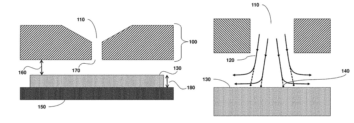
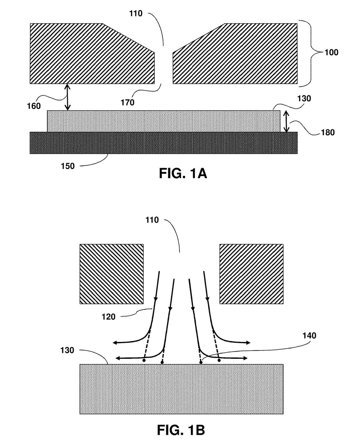
[0058]FIG. 1A provides a schematic diagram illustrating the general construction of a particle impactor and FIG. 1B illustrates an expanded view of a particle impactor to further illustrate the operational principal. As shown in these Figures, gas flow is directed through an intake aperture 110 in a sampling head 100 where it is accelerated towards an impact surface 130, which forces the gas to rapidly change direction, following flow paths or streamlines 120 under laminar fluid flow conditions. Due to their momentum, particles 140 entrained in the gas flow are unable to make the rapid change in direction and impact on the impact surface 130. In the embodiment shown in FIG. 1A and FIG. 1B, impact surface 130 is supported by impactor base 150. In embodiments, impact surface 130 comprises the receiving surface of a growth medium, such as agar, provided in a growth medium container or petri dish. Viable biological particles collected on the impact surface, for example, can subsequently...

example 2

justment of the Agar Media to Position it in an Optimum Position for Physical and Biological Collection Efficiencies

[0060]When using an active air sampler, where the sampling media is located in relationship to the air inlet impacts, the ability of the device to collect the particles as well as allow them to survive the impaction and grow proper during the incubation cycle depends in part on the separation distance 160 between the impact surface 130 and the exit 170 from the air inlet 110 (see FIGS. 1A-1B)

[0061]Samplers on the market today typically use a fixed location where the sampling inlet is a certain distance from the plate support points. Depending upon the media plate used the actual distance to the media can vary from quite close to rather far away (see, e.g., FIGS. 1C-1D). This can lead to either organisms not being impacted on the media and flowing away with the air flow, such as for media that is underfilled or positioned with too high a separation distance 160. Referri...


PUM

PropertyMeasurementUnit
optimal separation distanceaaaaaaaaaa
separation distanceaaaaaaaaaa

Abstract

Provided are impactors for detecting biologics having an adjustable separation distance between an impact surface and the intake aperture, including the exit of the intake aperture. The impactor has a sampling head having at least one intake aperture and an exit, an impactor base comprising an impact surface, wherein the impact surface opposibly faces the sampling head exit and is separated from the exit by a separation distance. The separation distance is continuously adjustable between a minimum separation distance and a maximum separation distance and can accommodate impact surfaces having different heights by positioning the impact surface, irrespective of height of the impact surface, at an optimal separation distance from the sample intake aperture, such as by a rotation-type mechanism with a change in distance indication provided to a user by a separation distance step indicator.

Description

CROSS-REFERENCE TO RELATED APPLICATIONS[0001]This application claims the benefit of priority from U.S. Provisional Patent Application No. 61 / 953,306 filed Mar. 14, 2014, which is hereby incorporated by reference in its entirety to the extent not inconsistent herewith.BACKGROUND OF INVENTION[0002]The invention is in the field of particle sampling, collection and analysis. The invention relates generally to devices and methods for sampling and characterizing particles in fluids include air and process chemicals (e.g., gases and liquids) for applications including the evaluation of contaminants in a range of cleanroom and manufacturing environments. More specifically, provided are impactors having a spatial adjustment to position an impact surface at an optimal separation distance from an intake aperture exit, independent of the height of the impact surface or the type of container in which the impact surface is located.[0003]Cleanrooms and clean zones are commonly used in semiconducto...

Claims


Application Information

Patent Timeline
Patent Type & Authority Patents(United States)
IPC IPC(8): G01N1/22G01N15/02G01N15/00
CPCG01N1/2208G01N15/0255G01N2015/0261G01N2015/0065
Inventor KETCHAM, CLIFFHARTIGAN, PAUL B.LAKSHMANAN, CHANDRASEKAR
Owner PARTICLE MEASURING SYST
Why Eureka
Try Eureka