Supercharged turbocompound hybrid engine apparatus

Active Publication Date: 2014-07-10
FPT MOTORENFORSCHUNG
View PDF10 Cites 18 Cited by
  • Summary
  • Abstract
  • Description
  • Claims
  • Application Information

AI Technical Summary

Benefits of technology

[0019]Therefore it is the main object of the present invention to provide a supercharged turbo-compound engine apparatus which allows to overcome the drawbacks above indicate. Within this object a first purposes is to provide a supercharged engine apparatus which allows a fuel consumption reduction and an increase of the power density. Another purpose of the present invention is to provide an engine apparatus which allow less smoke both in transient and

Problems solved by technology

However, the controllability of the mechanical driven low pressure compressor is hard to handle.
Although such undoubted advantages with respect to the mechanical schemes, anyway also known electric turbo-compound schemes does not allow to overcome ap

Method used


Image

  • Supercharged turbocompound hybrid engine apparatus
  • Supercharged turbocompound hybrid engine apparatus
  • Supercharged turbocompound hybrid engine apparatus

Examples


second embodiment

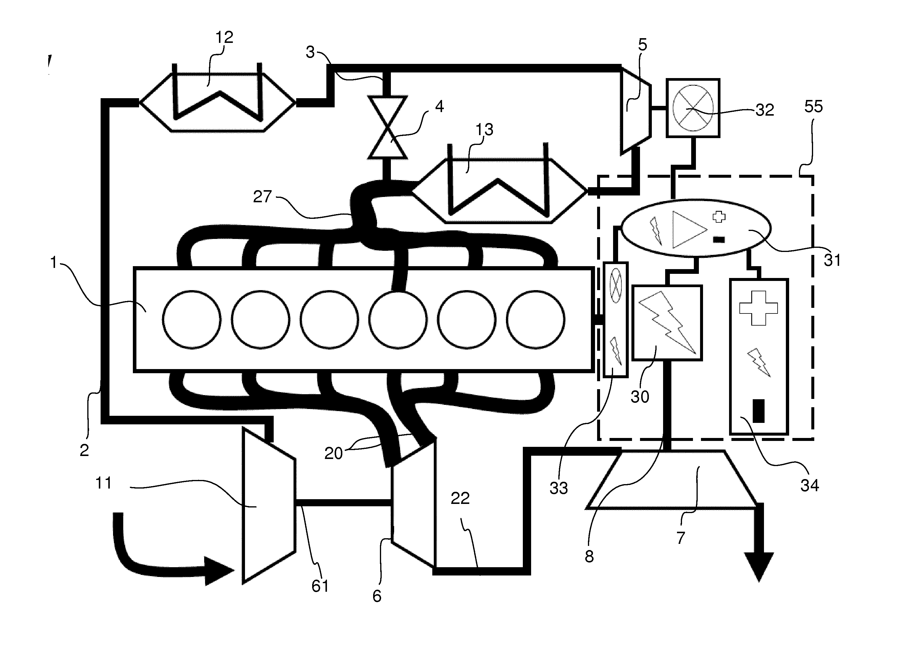
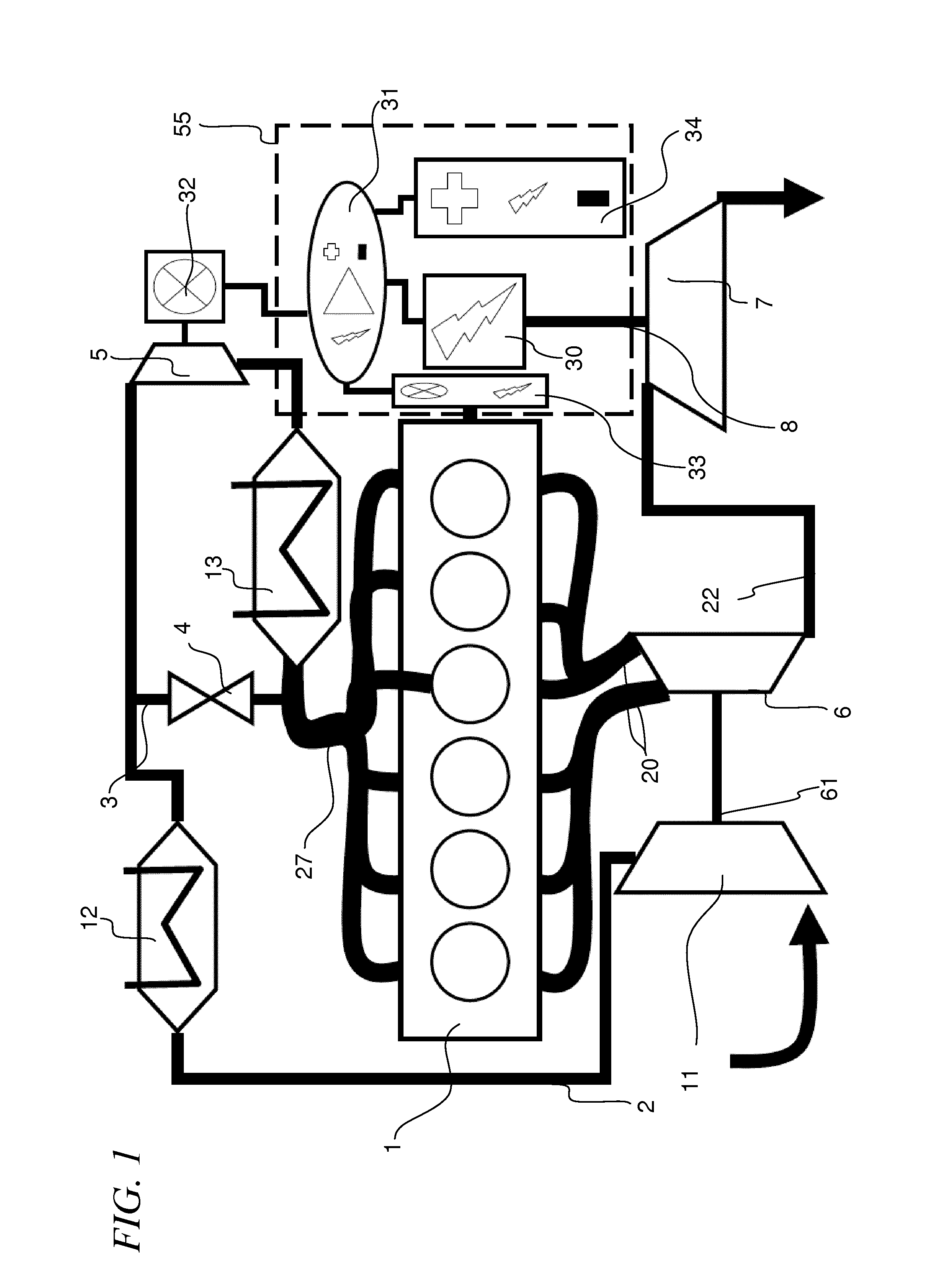
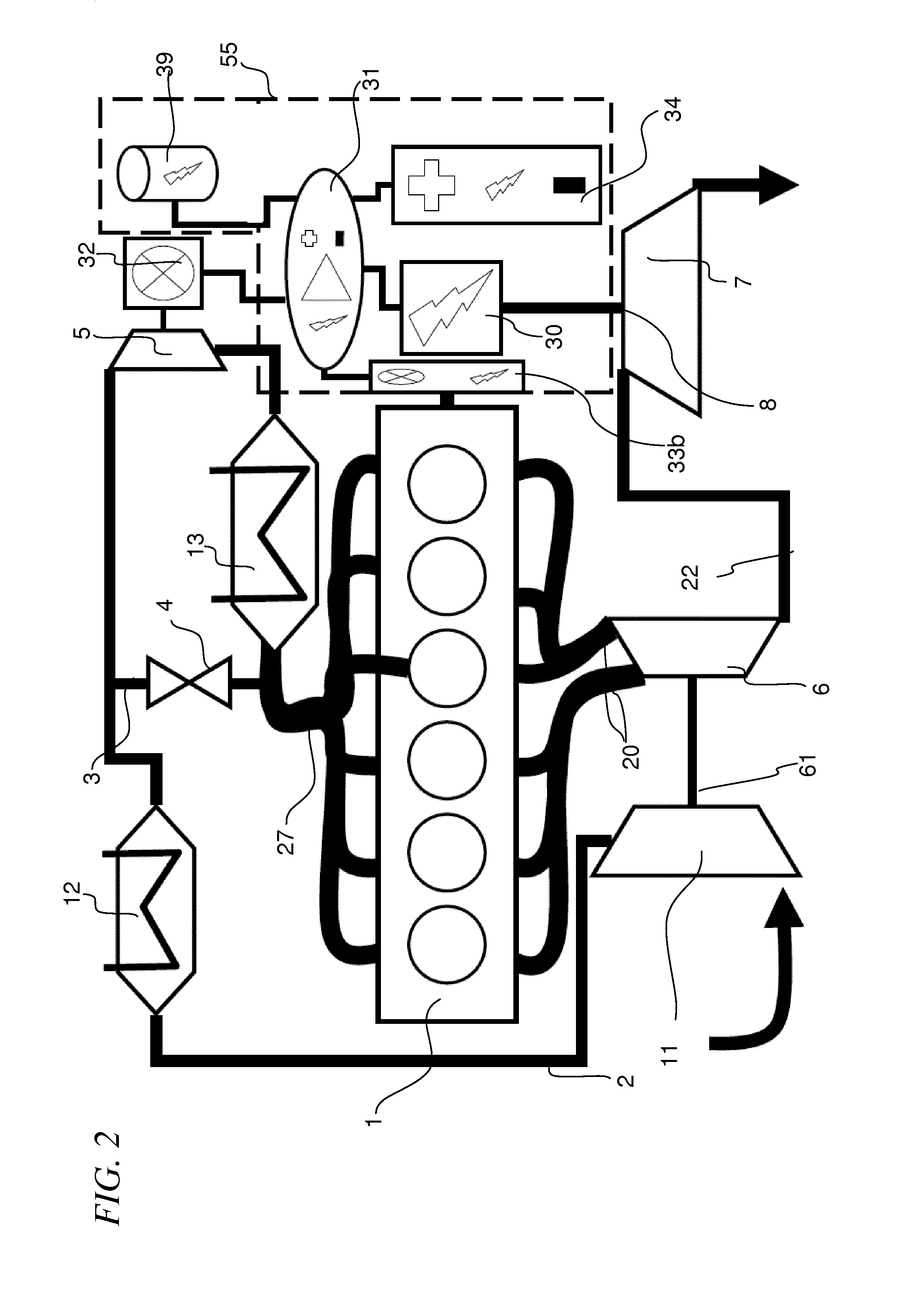
[0055] shown in FIG. 2, the electronic conversion means of electric torque converter 55 preferably comprises also a condenser 30 which is operatively managed by means of the inverter 31. The first electric motor 32 can get power out of the condenser 39 in case of a short term demand and out of the accumulator (battery / DC bus 34) in case of long term demand. This allows to improve the transient performance of the high pressure compressor 5. The electric power stored in the condenser 39 is controlled and distributed by the coupled inverter 31 to the first electric motor 32.

[0056]For the purpose of the present invention, the expression “short, term demand” means a demand of power having a duration shorter than a minute. A “short term demand” can be, for example, a demand of the driver to complete an overtaking, to ramp up over a short hilly area or to drive in a stone area with wheels loaded. On the contrary the expression “long term demand” means a demand of power whose duration is mo...

first embodiment

[0122]11) the present invention (iTC)(referred with empty rectangles).

[0123]In particular, the diagrams in the FIGS. 4-6 arc plotted in order to show comparisons respectively of said quantities: POFS, EPEG, PFRC.

[0124]From 800-1500 rpm the engine of the apparatus according the present invention runs as a two stage turbo-compound system (HPC and LPT are connected to the crankshaft). From 1500-2200 rpm the HPC 5 is disconnected (first electric motor 32 stopped), while the LPT 7 is always activated. FIG. 4 shows that the scheme of the present invention gives a surprising reduction in fuel saving starting from about 1500 RPM of the engine crankshaft, with respect to the known schemes. In line with this result also the diagram on FIG. 6 shows a higher PFRC from 1500 REM. And FIG. 5 shows a lower EPEG starting from about 1500 RPM of the engine crankshaft.

[0125]It seems that the total POFC is lower with respect to the TCD scheme, however the power density of the scheme according to the pre...


PUM


Abstract

The present invention is relative to a engine apparatus comprising a combustion engine, a low pressure compressor connected to a high pressure turbine. The apparatus also comprises a low pressure turbine and a high pressure compressor. The engine apparatus according to the invention comprises an electrical torque converter comprising at least an electric generator connected so as to be driven by said low pressure turbine and a first electric motor connected so as to drive said high pressure compressor. The torque converter also comprises electronic conversion means suitable to convert the electric energy produce by said electric generator and to power supply and control at least said first electric motor.

Description

CROSS REFERENCE TO RELATED APPLICATIONS[0001]The present application claims priority to PCT International Application No. PCT / EP2012 / 060119 filed an May 30, 2012, which application claims priority to European Patent Application No. 11168087.2 filed May 30, 2011.STATEMENT RE: FEDERALLY SPONSORED RESEARCH DEVELOPMENT[0002]Not Applicable.BACKGROUND[0003]The present invention relates to a super-charged turbo-compound hybrid engine apparatus and a control method of such apparatus, in particular for industrial vehicles. The invention finds application also in the field of marine engines, transport vehicles and agricultural applications, independently from the kind of feel, gasoline, diesel gas or hydrogen.STATE OF THE ART[0004]Two-stage turbocharging has been proposed as a means of achieving high efficiency in engines, in particular heavy duty diesel engines, such as those for industrial vehicles or ships. Two turbosuperchargers are placed in series on the engine intake line, driven by tu...

Claims


Application Information

Patent Timeline
IPC IPC(8): F02D28/00
CPCF02D28/00B60L1/003B60L7/14B60L15/20B60L15/2009B60L2240/36B60L2240/421B60L2240/423B60L2240/441B60L2240/443B60L2270/12B60L50/16B60L50/61F02B37/004F02B37/013F02B37/10F02B37/14F02B37/16F02B39/10F02B41/10F02M26/02Y02T10/12Y02T10/62Y02T10/64Y02T10/70Y02T10/7072Y02T10/72
Inventor MAIER, CHRISTIAN
Owner FPT MOTORENFORSCHUNG
Why Eureka
Try Eureka