Apparatus and method for medical scanning

A technology of scan line, imaging method

Inactive Publication Date: 2010-09-22
施格诺斯迪克斯有限公司
View PDF2 Cites 9 Cited by
  • Summary
  • Abstract
  • Description
  • Claims
  • Application Information

AI Technical Summary

Problems solved by technology

[0018] These high-cost, high-power-consuming devices are not suitable for point-of-care use outside of dedicated sonography equipment
In particular, these systems are not suitable for use with handheld

Method used


Image

  • Apparatus and method for medical scanning
  • Apparatus and method for medical scanning
  • Apparatus and method for medical scanning

Examples


Embodiment Construction

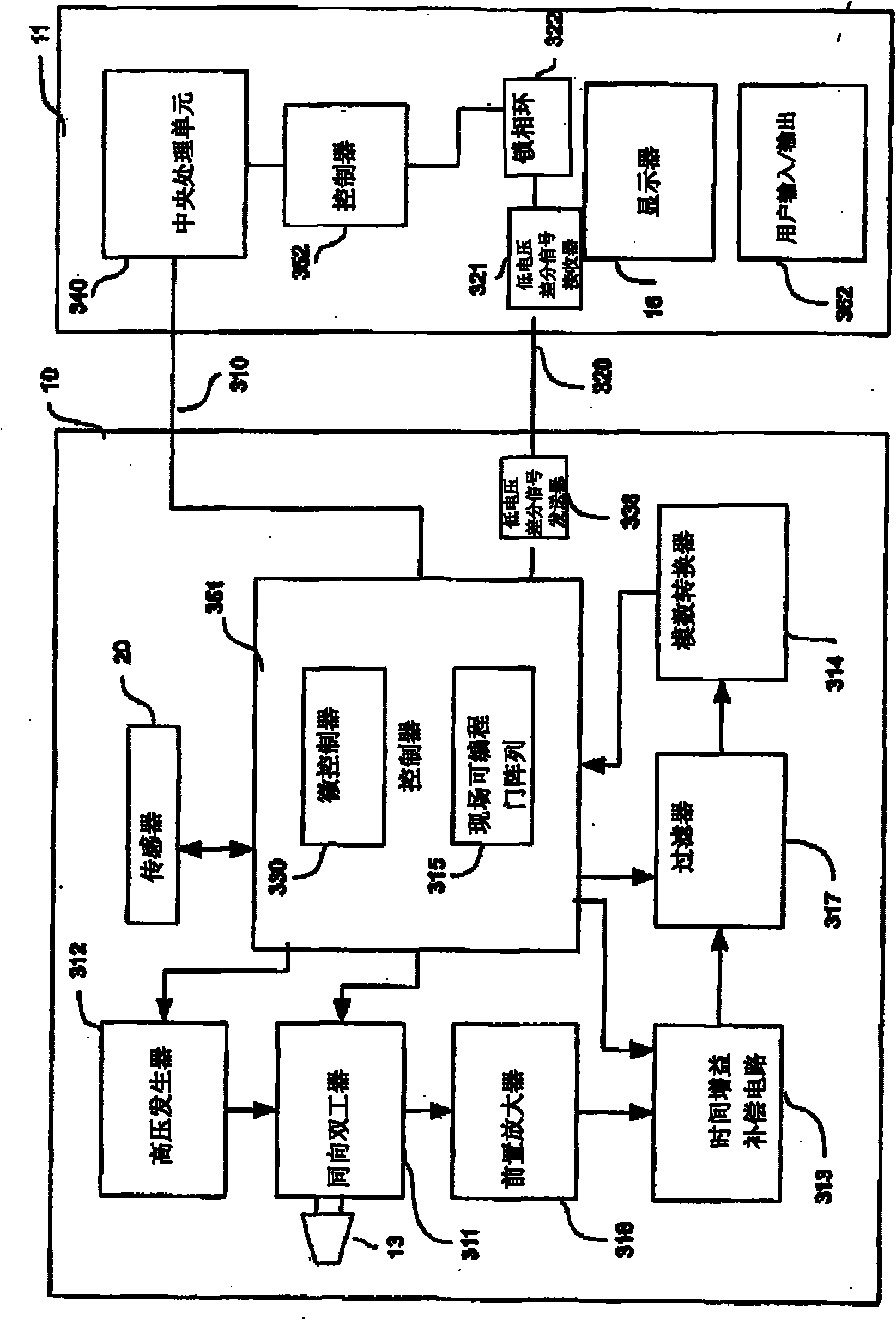
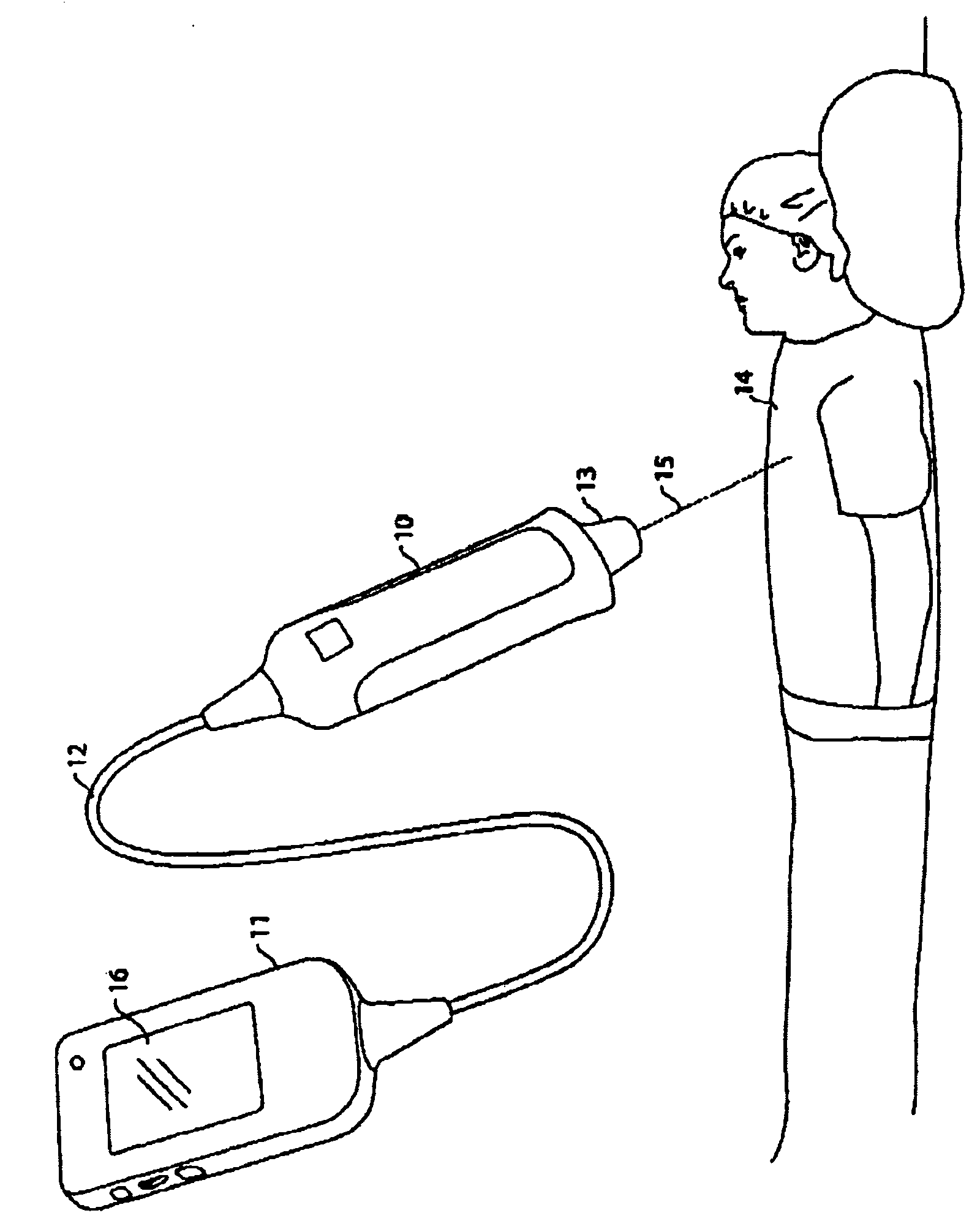
[0055] see figure 1, shows an ultrasonic scanning system according to an embodiment of the present invention. The figure shows a handheld ultrasonic detector unit 10 , a display and processing unit (DPU) 11 , a display screen 16 and a cable 12 connecting the detector unit with the display and processing unit 11 .

[0056] The probe unit 10 includes an ultrasound transducer 13 that can transmit pulsed ultrasound signals into a subject's body 14 and receive echoes returning from the subject's body 14 . In this embodiment, the transducer can only transmit and receive in a single direction at a fixed orientation to the detector unit, generating data for a single scan line 15 .

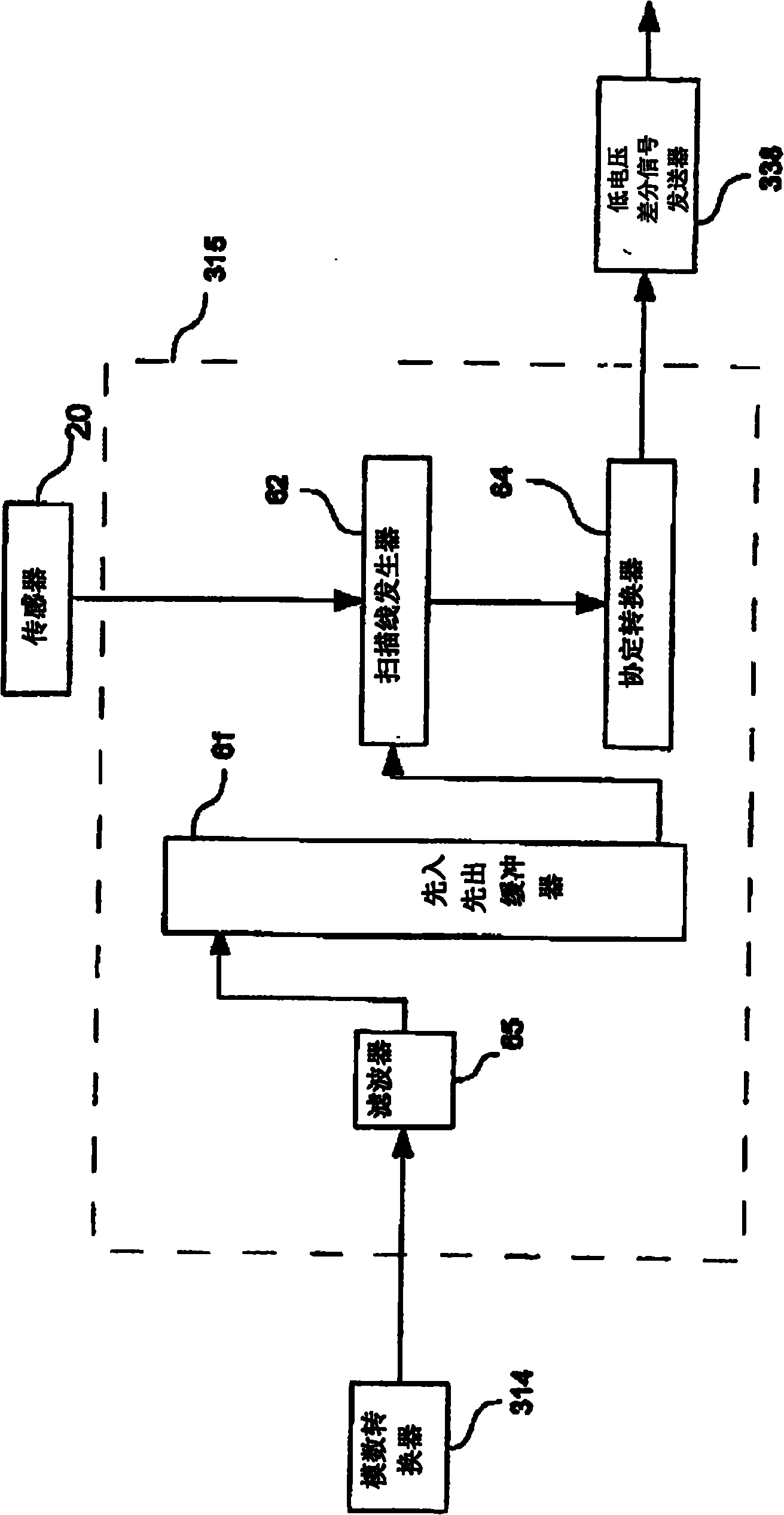
[0057] Such as figure 2 As shown, the probe also includes an orientation sensor 20 that can sense orientation or relative orientation about one or more axes of the probe. Thus, in general, the sensor can sense rotation about any or all axes of the detector unit, as indicated by the rotation arrows 24 ,...


PUM


Abstract

A hand held ultrasound imaging system with a probe unit having a transducer being adapted to transmit and receive ultrasonic signals and an orientation sensor adapted to sense the rotation of the probe unit, the output of the transducer and of the sensor being combined to produce a set of scanlines having a series of intensity values and a rotation value, the scanlines then being processed to produce a raster image for display on a display unit.

Description

technical field [0001] The present invention relates to an improved method and apparatus for ultrasonic scanning of objects, which has advantages in terms of cost and range of application. The method is particularly applicable in the field of hand-held ultrasound devices. Background technique [0002] Ultrasound was first used as a medical diagnostic imaging tool in the 1940s. This is based on A-mode (amplitude-mode) ultrasound, which is a form of echo-ranging. This simply gives a picture of echo intensity versus time, and by knowing the velocity of sound in the subject medium, the return wave from the transducer gives the distance of the feature. In order to obtain useful information from this scan line, the direction of the transmitted ultrasound beam is eg constant and known. [0003] In order to provide an imaging system, it is necessary to insonify a large area, at least a two-dimensional cross-section of an object. It is also necessary to receive echoes returning f...

Claims


Application Information

Patent Timeline
Patent Type & Authority Applications(China)
IPC IPC(8): A61B8/00
CPCA61B8/00A61B8/4254A61B2562/0219A61B8/462A61B8/14
Inventor 斯图尔特·加文·巴特利特保罗·詹姆斯·海尔川森
Owner 施格诺斯迪克斯有限公司
Why Eureka
Try Eureka