

Medicine discharging mechanism of medicine storing device
A technology of a drug storage device and a drug discharge mechanism, which is applied in the directions of storage device, transportation and packaging, can solve the problems of drug retention and unsmooth drug discharge, and achieves the effect of strong practicability and not easy to deform.
- Summary
- Abstract
- Description
- Claims
- Application Information
AI Technical Summary
Problems solved by technology
Method used
Image

Examples
Embodiment Construction
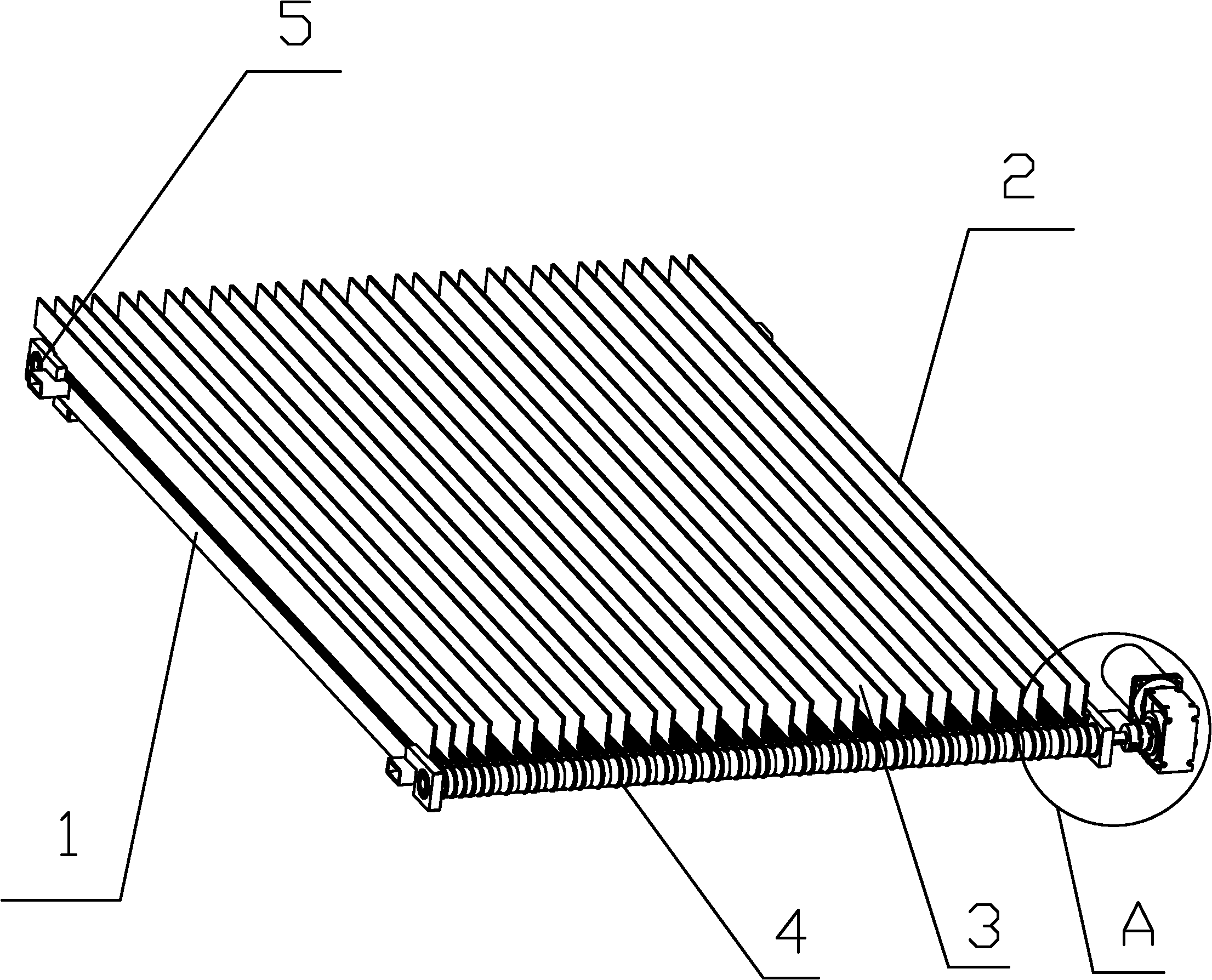
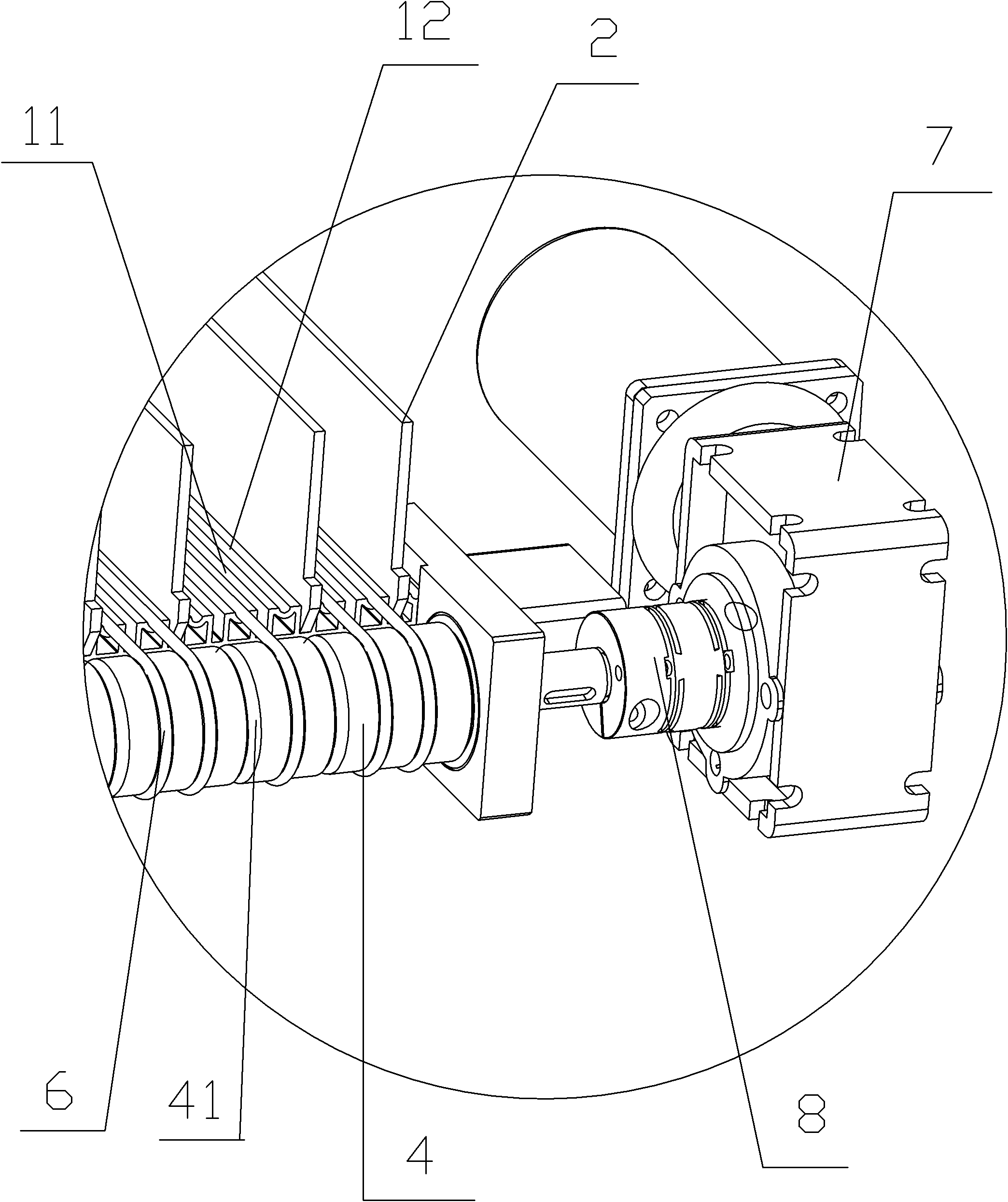
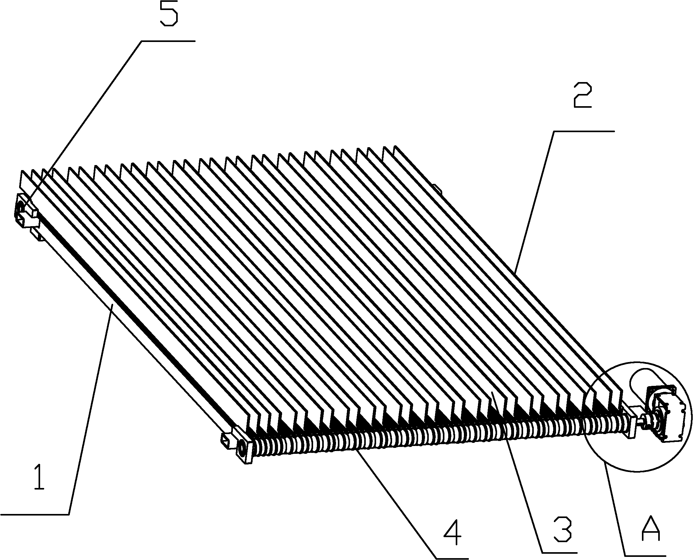
[0014] refer to figure 1 with figure 2 The medicine discharge mechanism of the medicine storage device of the present invention is described, the medicine discharge mechanism includes: a medicine tank bottom plate 1, a plurality of partitions 2, a driving wheel shaft 4, a driven shaft 5, a belt 6, a motor 7 and a coupling 8.
[0015] In this embodiment, the medicine tank bottom plate 1 is arranged horizontally inside the medicine storage device. Of course, the medicine tank bottom plate 1 can also be arranged inside the medicine storage device with an inclination at a certain angle, without affecting the drug delivery effect of the present invention. The medicine tank bottom plate 1 is composed of a plurality of bottom plates plugged and assembled. The number of the bottom plates used to form the medicine tank bottom plate 1 can be adjusted according to the size of the medicine storage device so as to realize the adjustment of the width of the medicine tank bottom plate 1. Th...
PUM
 Abstract
Description
Claims
Application Information