

Shuttle valve, shuttle valve driving type device, winding drum brake cylinder control loop and crane
A driven, shuttle valve technology, applied in the field of hydraulic control valves, can solve the problems of reduced service life, poor sealing, looseness, etc., and achieve the effects of wide application range, improved service life and reliable performance
- Summary
- Abstract
- Description
- Claims
- Application Information
AI Technical Summary
Problems solved by technology
Method used
Image

Examples
Embodiment Construction
[0092] The specific embodiments of the present invention will be described in detail below in conjunction with the accompanying drawings. It should be understood that the specific embodiments described here are only used to illustrate and explain the present invention, and the protection scope of the present invention is not limited to the following specific embodiments. .
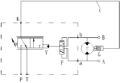
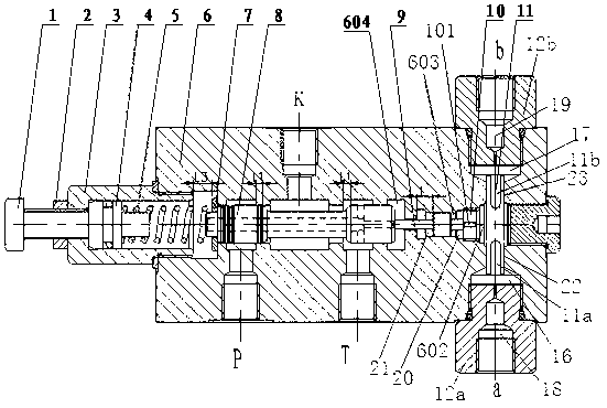
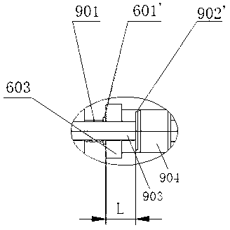
[0093] It should be noted, Figure 4 and Figure 5 Shown in is a specific embodiment of the shuttle valve actuated device of the present invention, wherein the shuttle valve actuated device is used as the hoist brake valve in the drum brake cylinder control circuit of the crane hoist mechanism. The shuttle valve-driven device of this specific embodiment integrates the shuttle valve F and the hydraulically controlled two-position three-way reversing valve Y of the present invention through the shared valve body 6, but it should be noted here that, Figure 5 The specific structure shown is only a preferred...
PUM
 Abstract
Description
Claims
Application Information