Eureka AIR delivers breakthrough ideas for toughest innovation challenges, trusted by R&D personnel around the world.

Vaporization coating template and application thereof

A template and evaporation technology is applied in the field of preparing multi-color display organic electroluminescent devices, which can solve the problems of mask deformation, difficulty in improving resolution, difficulty, etc., and achieve the effects of simple structure, easy cleaning, and non-deformation.

Active Publication Date: 2006-11-22
BEIJING VISIONOX TECH
View PDF1 Cites 9 Cited by
  • Summary
  • Abstract
  • Description
  • Claims
  • Application Information

AI Technical Summary

Problems solved by technology

[0010] a) Precise pixel preparation requires a high-quality evaporation mask, which leads to high cost of the mask and complicated preparation process;
[0011] b) The mask is easily deformed due to its own thermal expansion, which brings difficulties in precise alignment and makes it difficult to improve the resolution;
[0012] c) The gap of the mask is too small and easy to be blocked, which makes it too difficult to clean the mask later
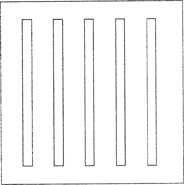
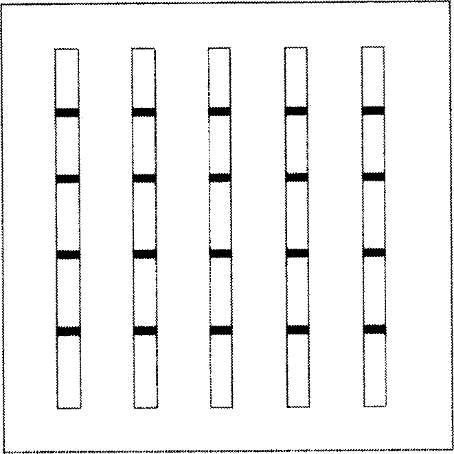
[0013] Many patents have been involved in improving the mask and improving the fineness of the mask. For example, in the Chinese patent application CN1404343A filed by LG and published on March 19, 2003, it is proposed to add a bridge to the sky of the template. connected technology solutions such as Figure 1A and B, but this technology cannot essentially solve the above-mentioned problems such as complex template preparation process, easy deformation and difficult cleaning

Method used

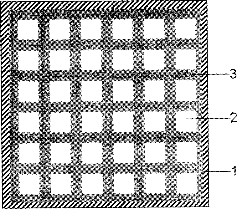

Image

  • Vaporization coating template and application thereof
  • Vaporization coating template and application thereof
  • Vaporization coating template and application thereof

Examples


Embodiment 1

[0041] First, prepare a limit shielding evaporation template:

[0042] Coating a layer of photoresist with a thickness equal to the thickness of the barrier on the template substrate of quartz glass, and then accurately exposing the substrate to obtain a limiting column with a width equal to one sub-pixel;

[0043] After the substrate is dried, cover the entire substrate with cobalt metal particles as a magnetic substance, and then vibrate the substrate. After the cavity formed by the limiting pillars is filled with cobalt metal particles, use a flat plate to block the evaporation template with a limit. Scrape to remove remaining cobalt particles.

[0044] Then, the limit-shielding evaporation template is used for evaporation to realize the full-color display organic electroluminescent device in RGB mode, including the following steps:

[0045] (a) The limit template is aligned with the substrate through the alignment system in the evaporation device, and the limit template i...

Embodiment 2

[0053] First, prepare a limiting shielding evaporation template according to the method of Example 1. The difference is that the cobalt particles as a magnetic substance are replaced with iron particles as a charged substance covering the entire substrate, and then the substrate is vibrated, and then the substrate is vibrated by the limiting column. After the formed cavity is filled with iron particles, use a flat plate to scrape the limit-shield evaporation template to remove the rest of the iron particles.

[0054] Then, the limit shielding evaporation template is used for evaporation to realize the full-color display organic electroluminescent device of RGBW mode, including the following steps:

[0055] (f) The limit template is aligned with the substrate through the alignment system in the evaporation device, and the limit template is bonded to the substrate after alignment (such as Figure 3A shown);

[0056] (g) Apply an electric field in the upper space of the substrat...


PUM


Abstract

The invention discloses a formwork in the deposition technology and using method of RGB preparing patterned full-color display organic electroluminescent element, which comprises the following parts: limit formwork base plate and barrier, wherein the base plate material is selected from glass, metal or ceramics; the barrier material is selected from metal, magnetic material. The invention is simple to manufacture and operate as well as clean, which isn't easy to deform.

Description

Technical field: [0001] The invention relates to a position-limiting shielding template used in an evaporation process, and a method for using the template in preparing a multi-color display organic electroluminescent device. Background technique: [0002] Today, with the development of multimedia technology and the advent of the information society, the requirements for the performance of flat panel displays are getting higher and higher. In recent years, three new display technologies: plasma display, field emission display and organic electroluminescent display have made up for the shortcomings of cathode ray tubes and liquid crystal displays to a certain extent. Among them, organic electroluminescent displays have a series of advantages such as self-luminescence, low-voltage DC drive, full curing, wide viewing angle, and rich colors, which are 1000 times that of liquid crystal displays, but their manufacturing costs are lower than those of liquid crystal displays with th...

Claims


Application Information

Patent Timeline
IPC IPC(8): C23C14/24C23C14/04
Inventor 邱勇吴空物高裕弟张德强
Owner BEIJING VISIONOX TECH
Why Eureka
Eureka Blog
Learn More