Automatic paper feeding device with clutch

A clutch and clutch control technology, applied in the direction of pile separation, object separation, object supply, etc., can solve problems affecting accuracy, collision loss, etc.

Active Publication Date: 2010-09-29
AVISION PRECISION IND (SUZHOU) CO LTD +1
View PDF0 Cites 8 Cited by
  • Summary
  • Abstract
  • Description
  • Claims
  • Application Information

AI Technical Summary

Problems solved by technology

[0003] The traditional gear clutch device uses a solenoid valve to control the center distance of the two transmission gears to control whether th...

Method used


Image

  • Automatic paper feeding device with clutch
  • Automatic paper feeding device with clutch
  • Automatic paper feeding device with clutch

Examples


Embodiment Construction

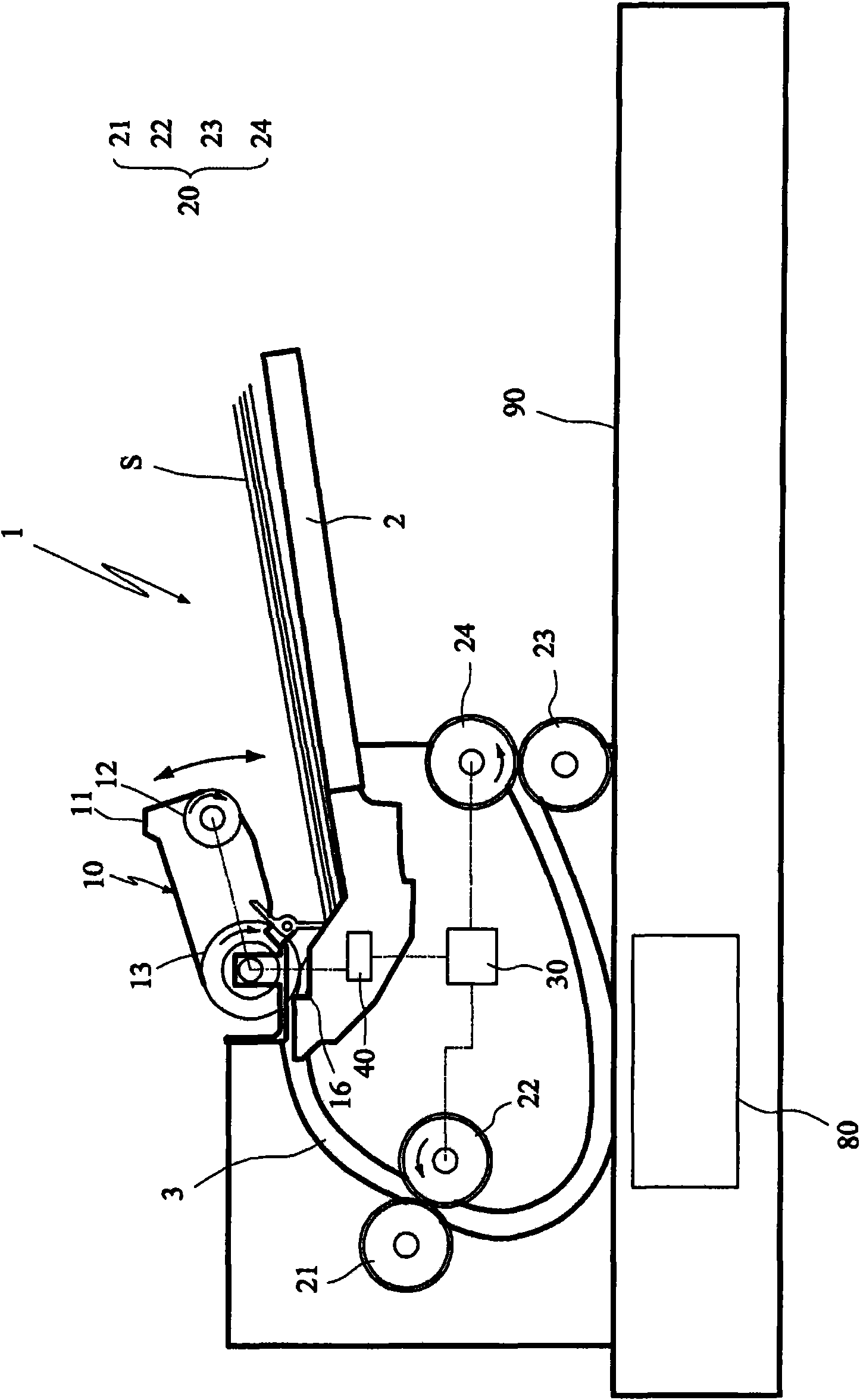
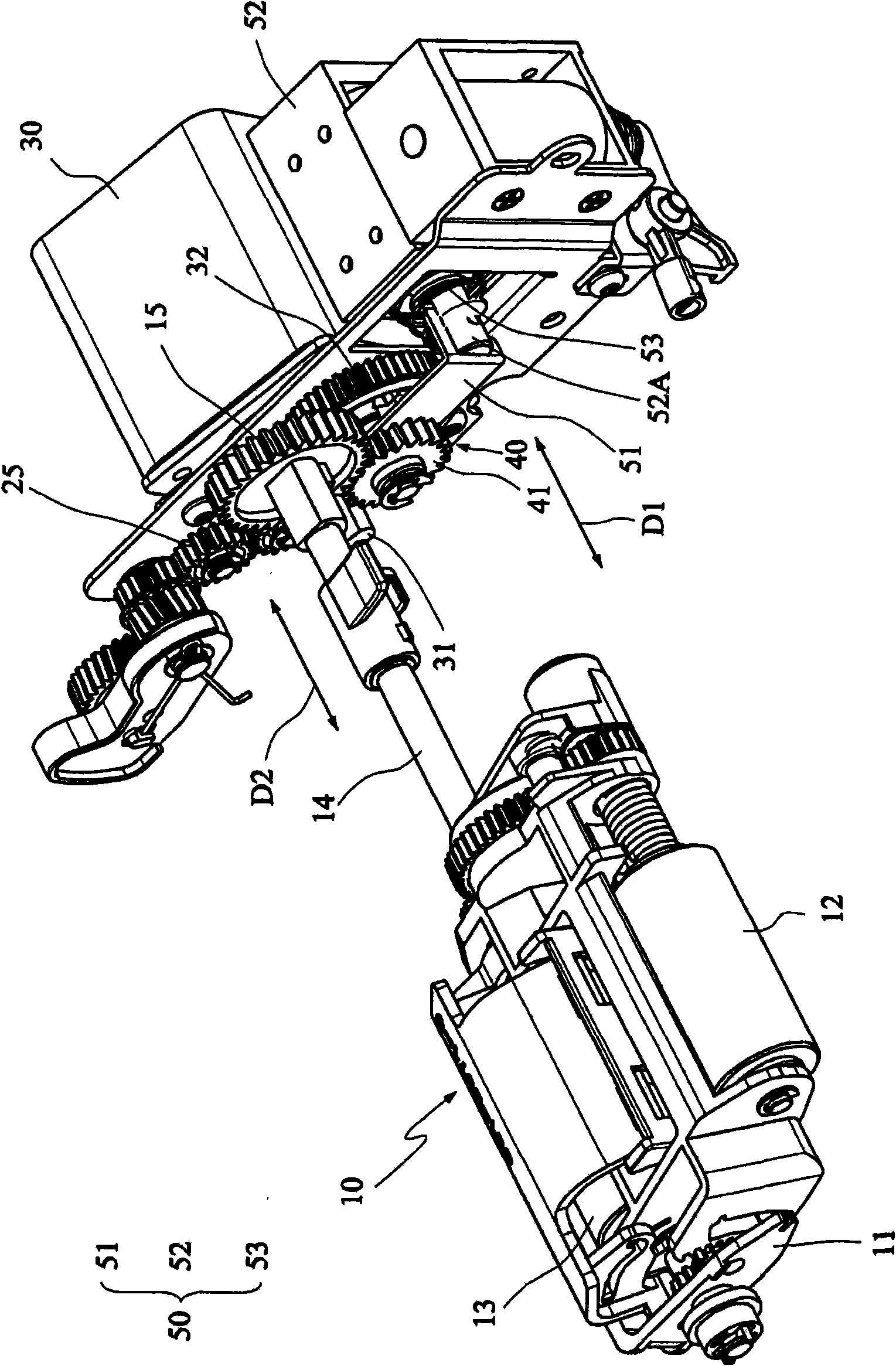
[0014] figure 1 A schematic diagram of an automatic sheet feeding device according to a preferred embodiment of the present invention is shown. figure 2 and 5 A partial three-dimensional schematic diagram of the automatic paper feeding device according to the preferred embodiment of the present invention is shown. like figure 1 , 2 As shown in FIG. 5 , the automatic paper feeding device 1 of this embodiment includes a paper picking mechanism 10 , a paper conveying mechanism 20 , a power source 30 and a clutch 40 . Of course, the automatic paper feeding device 1 may further include a casing 90 and a scanning module 80 that can move back and forth in the casing 90 .

[0015] The paper pick-up mechanism 10 is swingable for grabbing a paper S located in a paper cassette 2 and feeding the paper S into a channel 3 . In this embodiment, the paper pick-up mechanism 10 includes a power input shaft 14 and an input gear 15 . The input gear 15 is sleeved on the power input shaft 14...


PUM


Abstract

The invention relates to an automatic paper feeding device which comprises a paper fetching mechanism, a paper sheet transmission mechanism, a power source and a clutch. The power transmission mechanism is used for transmitting paper sheets grabbed in the paper fetching mechanism in a channel. The power source used for driving the paper fetching mechanism comprises a power output shaft and a first transmission gear, thereby respectively outputting and transferring power. The clutch comprises a second transmission gear and a power connection component. The second transmission gear and the first transmission gear are coaxially arranged. The power connection component is coaxially arranged between the first transmission gear and the second transmission gear and further connected with the first transmission gear. The power connection component carries out reciprocating movement along the axial direction, thereby selectively connecting and driving the second transmission gear. The second transmission gear is connected with the paper fetching mechanism, and the power source selectively drives the paper fetching mechanism through the clutch.

Description

technical field [0001] The present invention relates to an automatic paper feeding device, in particular to an automatic paper feeding device with a clutch to control the paper feeding procedure. Background technique [0002] The paper picking-type automatic paper feeding device used in traditional scanners usually includes a paper picking roller, a paper separation roller and several paper conveying rollers. The pickup rollers must be driven to move up and down to grab the paper to feed the separation rollers. Since the combination of pickup and separation rollers needs to be rotated intermittently and the combination of paper transport rollers must be rotated continuously, the combination of pickup and separation rollers must be driven separately from the combination of paper transport rollers. To achieve this requirement, two motors can be used to drive the combination of the pickup roller and the separation roller and the combination of the paper conveying roller respec...

Claims


Application Information

Patent Timeline
IPC IPC(8): B65H3/00B65H3/06B65H3/46B65H5/00B65H5/06H04N1/00
Inventor 郑松柏
Owner AVISION PRECISION IND (SUZHOU) CO LTD
Why Eureka
Try Eureka