Method for strengthening edges of tool and die based on laser transformation hardening

A technology of laser phase change hardening and tooling, which is applied in special data processing applications, instruments, electrical digital data processing, etc., can solve problems such as consumption, and achieve the effect of ensuring optimality and small material resources

Active Publication Date: 2010-09-29
ZHEJIANG UNIV OF TECH
View PDF5 Cites 8 Cited by
  • Summary
  • Abstract
  • Description
  • Claims
  • Application Information

AI Technical Summary

Problems solved by technology

[0006] In order to overcome the consumption of manpower and material resources in the prior art, and overcome the defects such as the collapse of the edge (or protrusion) of the tool and mold, the invention provides a kind of manpower and material resource consumption, which does not cause waste and can ensure the optimal offset distance. A revolutionary method for tool and mold surface strengthening based on laser phase transformation hardening

Method used


Image

  • Method for strengthening edges of tool and die based on laser transformation hardening
  • Method for strengthening edges of tool and die based on laser transformation hardening
  • Method for strengthening edges of tool and die based on laser transformation hardening

Examples


Embodiment 1

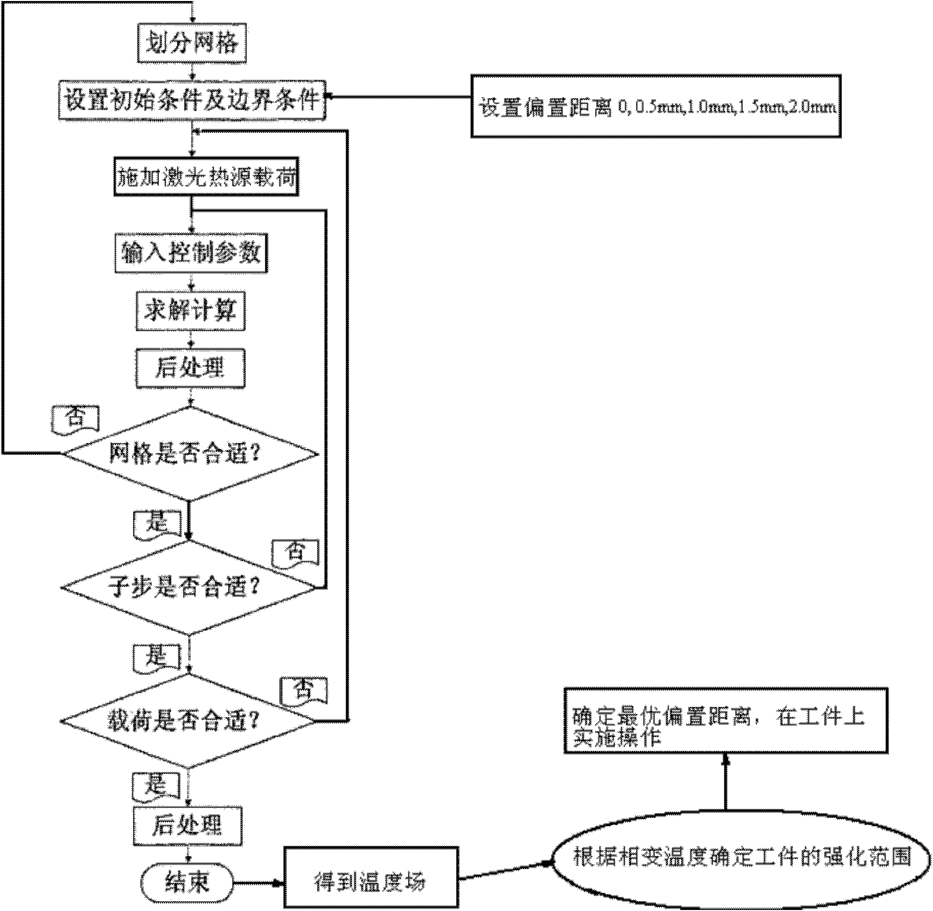
[0032] refer to figure 1

[0033] The method for strengthening the edge of the tool and mold based on laser phase transformation hardening comprises the following steps:

[0034] 1), select the laser intensified light source according to experience, set the light source parameters, the light source parameters include laser wavelength, power, scanning speed and spot diameter; obtain the parameters of the mold to be processed, the mold parameters include material properties, phase transition temperature , melting point and geometric size;

[0035] 2) Set the starting position of the strengthening light source, perform laser scanning, and pass compressed air to quickly cool the tool and mold to achieve the purpose of surface strengthening;

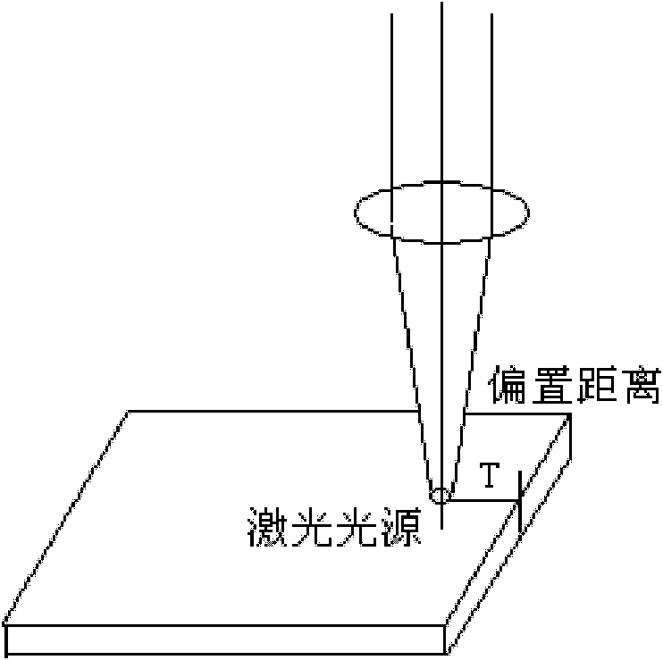
[0036] It is characterized in that: simulate and calculate the situation of the light source irradiating the tool and mold to obtain the optimal strengthening distance between the strengthening light source and the edge of the tool and mold...

Embodiment 2

[0047] combine Figure 2-10 , and the actual test further illustrates the present invention:

[0048] Select the quality of about 0.9kg, P20 plastic tool and die steel, strengthen the workpiece size is 15mm × 10mm × 10mm, and its edge is strengthened with H13 alloy powder. According to the intensified process, using cross-flow CO 2 The laser power required by the laser is P=1.5kW, the spot diameter D=4mm, and the powder is fed synchronously. Specific steps are as follows:

[0049] (1) The simulation adopts the same process as the actual one—synchronous powder feeding method, and the surface of the same matrix material plastic tool and die steel P20 is clad with H13 powder. The laser process parameters are shown in Table 1:

[0050] Table 1 Laser process parameters

[0051] Process parameters

Laser scan rate v(m / s)

0.005

Laser power P(KW)

1.5

Spot size D(mm)

4

[0052] (2) Select a Gaussian heat source model similar t...


PUM

PropertyMeasurementUnit
melting pointaaaaaaaaaa

Abstract

The invention relates to a method for strengthening edges of a tool and a die based on laser transformation hardening. The method comprises the following steps of: selecting a laser strengthening light source according to experience, and setting light source parameters, wherein the light source parameters comprise laser wavelength, power, scanning speed and spot diameter; obtaining the parameter of the tool and the die to be processed, wherein the tool and die parameters comprise material properties, transformation temperature, melting point and geometry size; setting a starting position of the strengthening light source, carrying out laser scanning, and fast cooling the tool and the die through compressed air so as to achieve the purpose of surface strengthening; and carrying out simulation calculation under the condition that the light source irradiates the tool and the die so as to obtain the optimal strengthening distance between the strengthening light source and the edges of thetool and the die, and enabling the distance between the starting position of the strengthening light source and the edges of the tool and the die to be equivalent to the optimal strengthening distance. The invention consumes less human and material resources, can not produce waste, can ensure the optimality of an offset distance, and especially has greater advantages on laser strengthening of a single product.

Description

technical field [0001] The invention relates to a laser surface strengthening treatment method, in particular to a laser phase transformation hardening method for the edge of a mold. technical background [0002] The main failure mode of tooling is surface wear. Therefore, it is the most economical and effective method to use surface treatment technology to improve the comprehensive performance of the surface of the tool and mold such as strength, hardness, wear resistance, etc., to reduce wear and improve the service life of the tool and mold. At present, a variety of surface strengthening treatment technologies have been developed in the tool and mold industry. The common ones are: thermal spraying, plasma chemical heat treatment, ion implantation technology, vapor deposition technology, TD treatment, electroplating and electroless plating, brush plating, etc. With the development of large-scale products, especially the emergence of high-speed, high-efficiency and high-pr...

Claims


Application Information

Patent Timeline
Patent Type & Authority Applications(China)
IPC IPC(8): C21D1/09G06F17/50
Inventor 骆芳陈智军胡夏夏杨友东姚建华
Owner ZHEJIANG UNIV OF TECH
Why Eureka
Try Eureka