
Air-lar machine negative pressure sucking-off plant

A technology of negative pressure suction and web forming machine, which is applied in the direction of textiles, papermaking, non-woven fabrics, etc., and can solve the problems of web floating, continuous and stable production, pleating, etc.

Inactive Publication Date: 2010-09-29
DALIAN TIANMA SOLUBILITY NONWOVEN
View PDF6 Cites 18 Cited by
  • Summary
  • Abstract
  • Description
  • Claims
  • Application Information

AI Technical Summary

Problems solved by technology

[0002] Before the prior art air-laid machine is not equipped with a negative pressure suction device, when the output fiber web of the air-laid machine is conveyed through the output curtain and enters the hot rolling mill for hot rolling, the surface temperature of the hot rolling mill roll is in a high temperature state. A large hot air flow is generated between the rolling mills. Affected by this hot air flow, the fiber web on the output curtain will float and pleat at the entrance of the hot rolling mill. In severe cases, holes will be formed, which seriously affects the product. quality, unable to produce continuously and stably

Method used


Image

  • Air-lar machine negative pressure sucking-off plant
  • Air-lar machine negative pressure sucking-off plant
  • Air-lar machine negative pressure sucking-off plant

Examples


Embodiment Construction

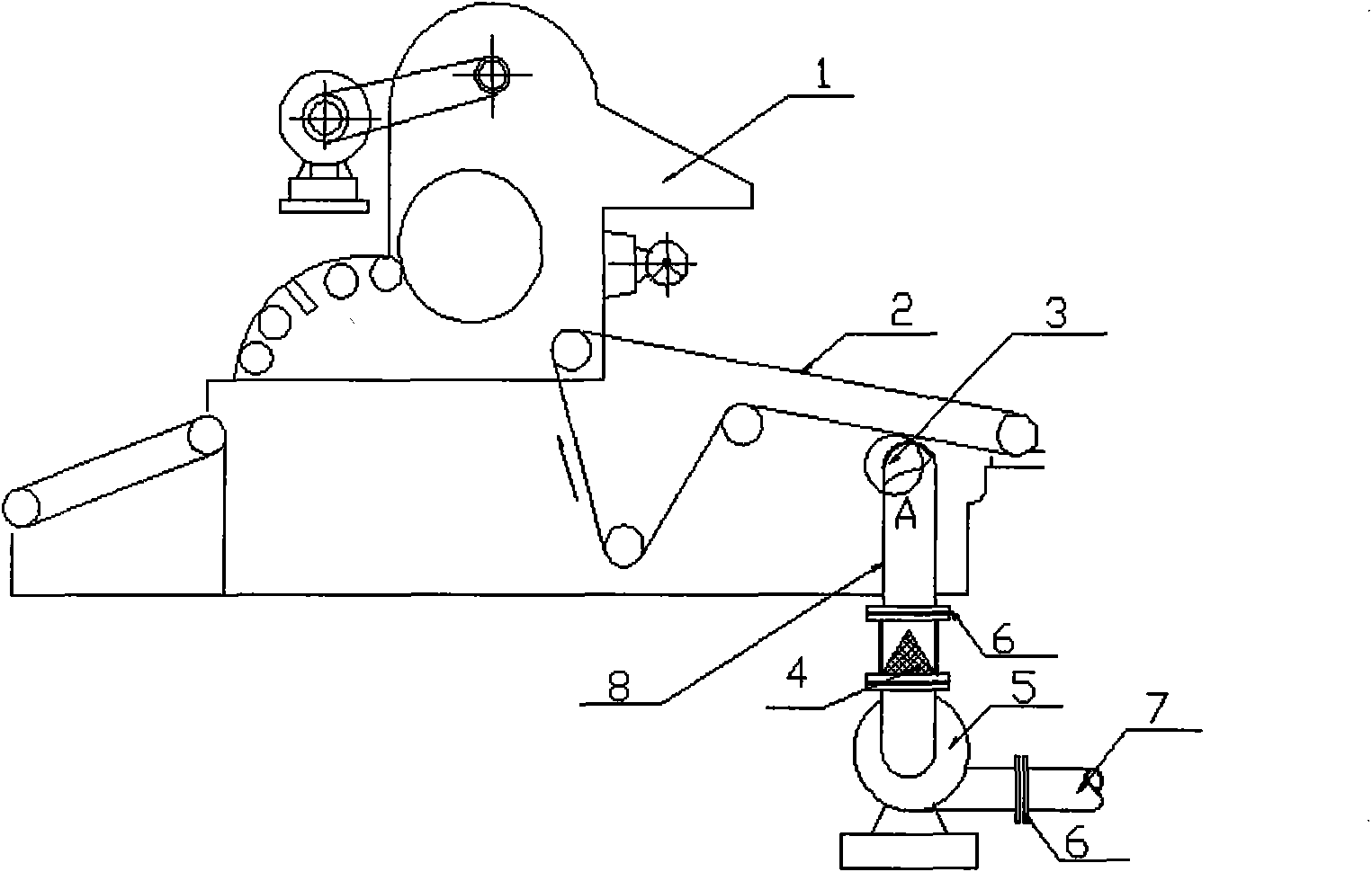
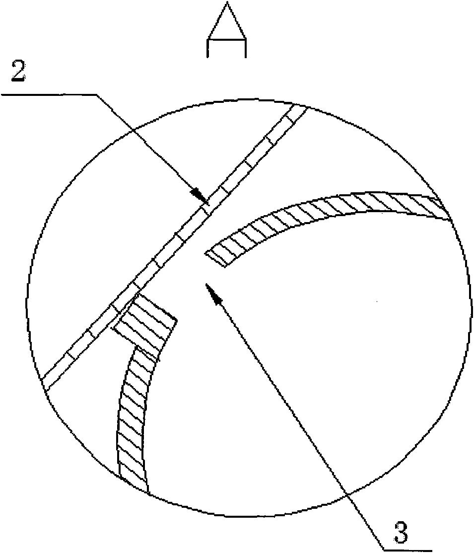
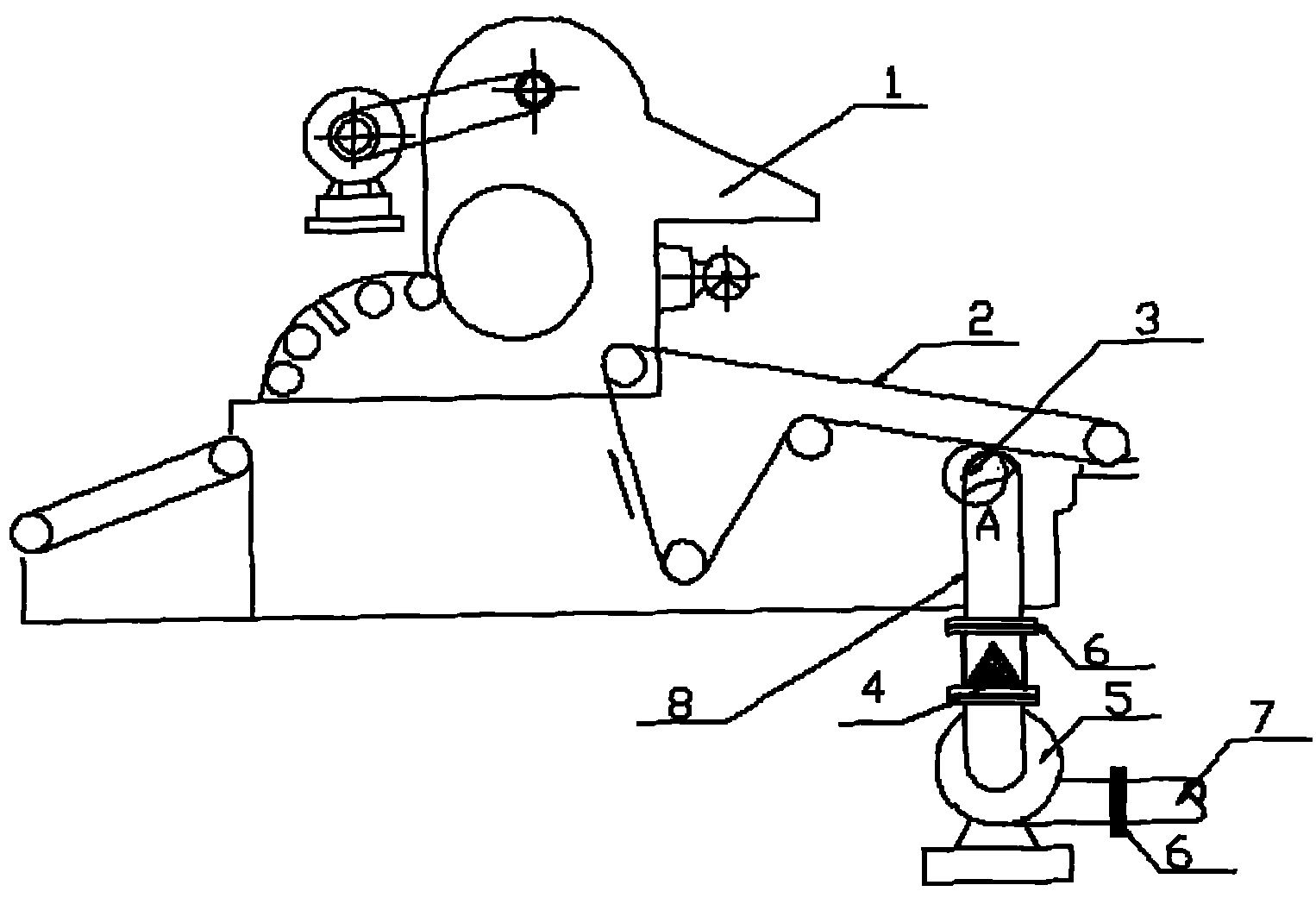
[0013] Such as figure 1 As shown, the negative pressure suction device of the air-laid machine includes an air-laid machine 1, an output curtain 2, a suction port 3, a filter 4, a suction fan 5, a connecting flange 6, an exhaust pipe 7 and an air suction pipe 8, The suction port 3 of the negative pressure suction device is connected to the bottom of the output curtain 2, the suction pipe 8 is connected to the suction port 3, the bottom end of the suction pipe 8 is connected with a suction fan 5, and the side of the suction fan 5 is connected with a discharge fan. Trachea 7, the suction pipe 8 is equipped with a connecting flange 6, and the air inlet of the suction fan 5 is provided with a filter 4, which is used to filter the remaining cotton on the condensed cotton to avoid blocking the suction fan. A coupling flange 6 is installed, wherein the output curtain 2 is connected to the air-laid machine 1 . When the negative pressure suction device is working, the suction fan 5 is...


PUM


Abstract

The invention discloses an air-lar machine negative pressure sucking-off plant, which comprises an exhaust inlet, an air intake duct, an induced-draught fan and an exhaust pipe, wherein the exhaust inlet is connected to the bottom end of an output curtain and is also connected with the air intake duct; the bottom end of the air intake duct is connected with the induced-draught fan; and the side of the induced-draught fan is connected with the exhaust pipe. The air-lar machine negative pressure sucking-off plant of the invention generates downward artificial flowing air flow between the output curtain and a hot milling, thereby offsetting the upward air flow generated by the hot milling at high temperature, and enabling a fibre web to enter the hot milling steadily. The plant is simple and practical, and the exhaust pipe is a PPR plastic tube with the diameter of 150mm; the connection part of the exhaust pipe is connected by a PPR interface and a bend tube, thereby being convenient to assembly and disassembly; and a filter is arranged on the air inlet of the induced-draught fan to filter the remained cotton on filter condense cotton so as to prevent the plug of the induced-draught fan.

Description

technical field [0001] The invention relates to a negative pressure suction device of an air-laid machine. Background technique [0002] Before the prior art air-laid machine is not equipped with a negative pressure suction device, when the output fiber web of the air-laid machine is conveyed through the output curtain and enters the hot rolling mill for hot rolling, the surface temperature of the hot rolling mill roll is in a high temperature state. A large hot air flow is generated between the rolling mills. Affected by this hot air flow, the fiber web on the output curtain will float and pleat at the entrance of the hot rolling mill. In severe cases, holes will be formed, which seriously affects the product. Quality cannot be produced continuously and stably. Contents of the invention [0003] The purpose of the present invention is to provide an air-laid air-laid that can generate artificial downward flow airflow between the output curtain and the hot rolling mill, th...

Claims


Application Information

Patent Timeline
IPC IPC(8): D04H1/44D04H1/00
Inventor 刘建为张成猛
Owner DALIAN TIANMA SOLUBILITY NONWOVEN
Learn More