Blade arrangement mode of compressor blade row for enhancing air load and stability

An aerodynamic load and stability technology, which is applied to components of pumping devices for elastic fluids, machines/engines, liquid fuel engines, etc., can solve the difficulty of increasing the aerodynamic load at small angles of attack on the blade cascade and improve the effect of aerodynamic stability To achieve the effect of improving the aerodynamic stability of the cascade, improving the aerodynamic stability and high efficiency

Inactive Publication Date: 2010-09-29
NORTHWESTERN POLYTECHNICAL UNIV
View PDF1 Cites 2 Cited by
  • Summary
  • Abstract
  • Description
  • Claims
  • Application Information

AI Technical Summary

Problems solved by technology

[0006] In order to overcome the disadvantages of the prior art that it is difficult to increase the aerodynamic load of the cascade at a small angle of attack and the ef...

Method used


Image

  • Blade arrangement mode of compressor blade row for enhancing air load and stability
  • Blade arrangement mode of compressor blade row for enhancing air load and stability

Examples


Embodiment 1

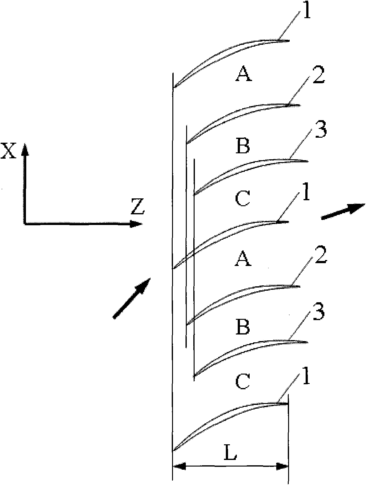
[0024]The arrangement of the cascade in this embodiment is as follows: the front edges of the same row of blades along the tangential direction of the cascade, that is, the X direction, are arranged differently in the front and rear of the cascade axial direction, that is, the Z direction. In the same blade set, taking the axial position of the leading edge of the first blade as the axial positioning reference, the second adjacent blade 2 is located on the side of the blade pot surface of the first blade 1, and its leading edge position Relative to the positioning reference, move back a certain distance along the axial direction of the cascade, and the moved distance is 11% of the axial chord length L of the first blade 1; the third blade 3 adjacent to the second blade 2 is located at On the side of the surface of the blade pot of the second blade 2, the axial position of its leading edge moves back a certain distance relative to the leading edge of the second blade 2 along the...

Embodiment 2

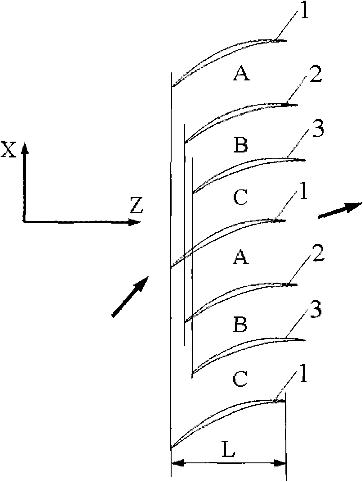
[0028] The arrangement of the cascade in this embodiment is as follows: the front edges of the same row of blades along the tangential direction of the cascade, that is, the X direction, are arranged differently in the front and rear of the cascade axial direction, that is, the Z direction. In the same blade set, taking the axial position of the leading edge of the first blade as the axial positioning reference, the second adjacent blade 2 is located on the side of the blade pot surface of the first blade 1, and its leading edge position Relative to the positioning reference, move back a certain distance along the axial direction of the cascade, and the moved distance is 7% of the axial chord length L of the first blade 1; the third blade 3 adjacent to the second blade 2 is located at On the side of the surface of the blade pot of the second blade 2, the axial position of its leading edge moves back a certain distance relative to the leading edge of the second blade 2 along the...

Embodiment 3

[0030] The arrangement of the cascade in this embodiment is as follows: the front edges of the same row of blades along the tangential direction of the cascade, that is, the X direction, are arranged differently in the front and rear of the cascade axial direction, that is, the Z direction. In the same blade set, taking the axial position of the leading edge of the first blade as the axial positioning reference, the second adjacent blade 2 is located on the side of the blade pot surface of the first blade 1, and its leading edge position Relative to the positioning reference, move back a certain distance along the axial direction of the cascade, and the moved distance is 15% of the axial chord length L of the first blade 1; the third blade 3 adjacent to the second blade 2 is located at On the side of the surface of the blade pot of the second blade 2, the axial position of its leading edge moves back a certain distance relative to the leading edge of the second blade 2 along th...


PUM


Abstract

The invention discloses a blade arrangement mode of a compressor blade row for enhancing air load and stability. Every three adjacent blades in the same blade row form a group; based on the axial position of the front edge of a first blade (1), a second blade (2) adjacent to the first blade is positioned on one side of the blade basin surface of the first blade; the front edge of the second blade (2) moves backwards along the axial direction of the blade row and the movement distance accounts for 7 to 15 percent of the axial chord length L of the first blade; a third blade (3) adjacent to the second blade is positioned on one side of the blade basin surface of the second blade; the front edge of the third blade moves backwards relatively to the front edge of the second blade (2) along the axial direction of the blade row and the movement distance accounts for 5 to 15 percent of the axial chord length of the first blade (1); and the third blade rotates around the front edge of the third blade by 1 to 3 degrees. Three different air flow passages are formed in one blade row, and air flow in the air flow passages can enhance the air stability of an air compressor and the air load of the blade is remarkably enhanced under the condition that the blade shape design bending deflection of each blade is not changed.

Description

1. Technical field [0001] The invention relates to the field of axial-flow impeller machinery, and relates to a vane arrangement method of a compressor vane cascade that increases aerodynamic load and stability. 2. Background technology [0002] Improving the aerodynamic load of the axial flow compressor and reducing the number of compressor stages are the requirements for the compressor of modern high thrust-to-weight ratio aviation gas turbine engines. In the compressor design, increasing the aerodynamic load of the compressor blades often results in the reduction of the aerodynamic stability of the compressor. For this reason, many schemes have been adopted in the aerodynamic design and structural design to improve the aerodynamic stability of the compressor. The existing conventional axial flow compressor blades adopt a completely axisymmetric and evenly distributed design scheme. When the inlet airflow angle of attack is large, the airflow boundary layer on the back su...

Claims


Application Information

Patent Timeline
IPC IPC(8): F04D29/34F04D29/66
Inventor 廖明夫刘前智王俨剀王四季杨伸记
Owner NORTHWESTERN POLYTECHNICAL UNIV
Why Eureka
Try Eureka