A Rotating Blade Arrangement for Improving the Aerodynamic Performance of Axial Flow Compressor

An axial flow compressor and rotating blade technology, which is applied to machines/engines, components of pumping devices for elastic fluids, mechanical equipment, etc., can solve the problems of limited improvement of turning angle and increased flow loss at design points, etc. Achieve the effect of not reducing aerodynamic stability, improving flow conditions, and improving aerodynamic efficiency

Inactive Publication Date: 2012-02-01
NORTHWESTERN POLYTECHNICAL UNIV
View PDF1 Cites 0 Cited by
  • Summary
  • Abstract
  • Description
  • Claims
  • Application Information

AI Technical Summary

Problems solved by technology

However, when the consistency increases to a certain value, the effect of improving the turning angle at the design point with a small angle of attack is very limited, and the flow loss near the design point increases significantly

Method used


Image

  • A Rotating Blade Arrangement for Improving the Aerodynamic Performance of Axial Flow Compressor
  • A Rotating Blade Arrangement for Improving the Aerodynamic Performance of Axial Flow Compressor
  • A Rotating Blade Arrangement for Improving the Aerodynamic Performance of Axial Flow Compressor

Examples


Embodiment 1

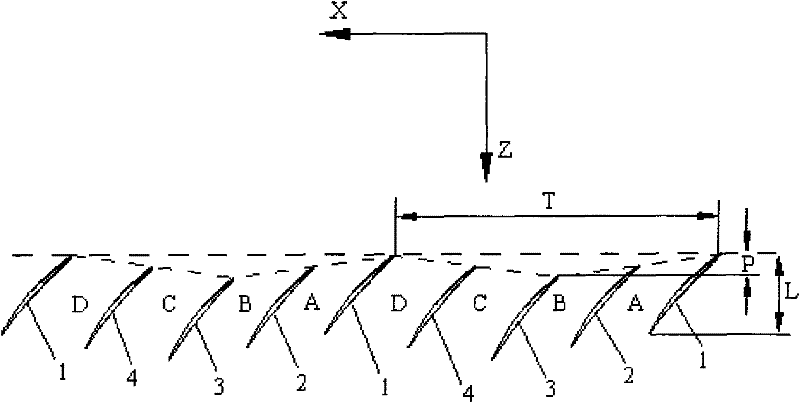
[0029] The arrangement of blades in the rotating blade row of the present embodiment is as follows: take N=2, and in the circumferential direction X of the blade row, a blade group is formed by 5 adjacent blades, and the fifth blade is the blade group in the next blade group. The first blade 1; in the same blade group, the second blade 2 is located on the side of the back surface of the first blade 1, the third blade 3 is located on the side of the back surface of the second blade 2, and the fourth The first blade 4 is positioned on the side of the blade back surface of the third blade 3, the first blade 1 is positioned on the side of the blade back surface of the fourth blade 4 in the previous blade group, and so on. The Z position of the compressor axial direction of the leading edge of each blade in a blade group forms a triangular wave, the leading edge of the first blade 1 in the blade group is located at the crest of the triangular wave, and the leading edge of the third ...

Embodiment 2

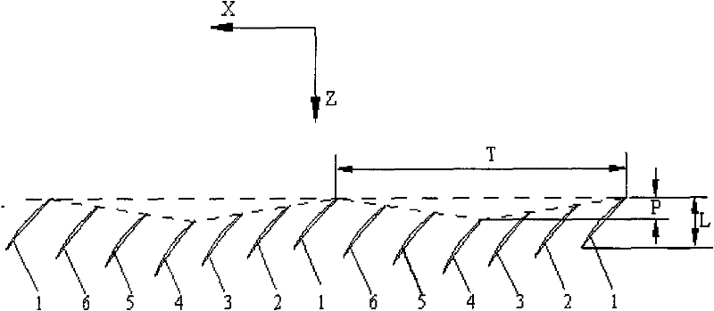
[0032] The arrangement of blades in the rotating blade row of this embodiment is as follows: take N=3, and in the circumferential direction X of the blade row, a blade group is formed by 7 adjacent blades, and the seventh blade is the blade group in the next blade group. The first blade 1; in the same blade group, the second blade 2 is located on the side of the back surface of the first blade 1, the third blade 3 is located on the side of the back surface of the second blade 2, and the fourth The first blade 4 is positioned at the blade back surface side of the third blade 3, the fifth blade 5 is positioned at the blade back surface side of the fourth blade 4, and the sixth blade 6 is positioned at the blade back surface side of the fifth blade 5. side, the first blade 1 is located on the side of the back surface of the fourth blade 6 in the previous blade group, and so on. The Z position of the compressor axial direction of the leading edge of each blade in a blade group for...

Embodiment 3

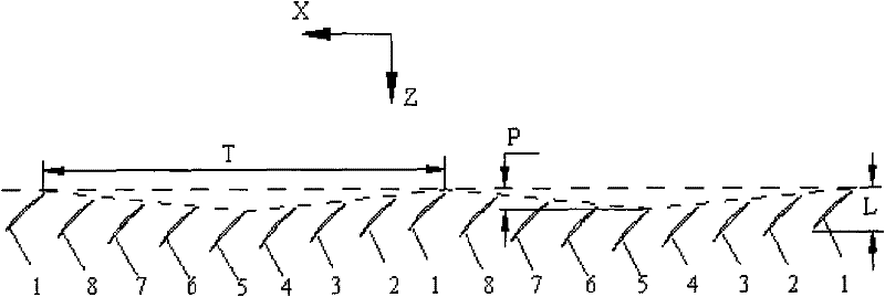
[0035] In this embodiment, the arrangement of the blades in the rotating blade row is as follows: take N=4, and in the circumferential direction X of the blade row, a blade group is formed by 9 adjacent blades, and the ninth blade is the blade group in the next blade group. The first blade of 1. In the same blade group, the second blade 2 is located on the side of the blade back surface of the first blade 1, the third blade 3 is located on the side of the blade back surface of the second blade 2, and the fourth blade 4 is located on the side of the blade back surface of the first blade 1. The blade back surface side of three blades 3, the fifth blade 5 is positioned at the blade back surface side of the fourth blade 4, the sixth blade 6 is positioned at the blade back surface side of the fifth blade 5, and the seventh blade 6 is positioned at the blade back surface side of the fifth blade 5. The blade 7 is located on the side of the blade back surface of the sixth blade 6, the...


PUM


Abstract

The present invention is a rotating blade arrangement for improving the aerodynamic performance of an axial flow compressor. The blades of the axial flow compressor are periodically arranged along the circumferential direction X, and each cycle is composed of 2N blade passages. The blades arranged in each cycle The line connecting the axial position of the leading edge forms a triangular wave; the leading edges of the 1st blade (1) and the 2N+1th blade in each cycle are located at the crest of the triangular wave, and the leading edge of the N+1th blade is located at the triangular wave at the trough. Under the condition that the blade camber is unchanged and the aerodynamic stability is not lowered and may be improved, the invention can increase the pressurization ratio of the rotating blade row at the design point with a small angle of attack, increase the clogging flow rate, and not reduce the efficiency. With the compressor of the present invention, the state of zero angle of attack or even negative angle of attack can be selected as its aerodynamic design point, not only can obtain a higher boost ratio and higher efficiency near the design point, but also have a larger stability margin of the compressor .

Description

1. Technical field [0001] The invention relates to the field of axial-flow impeller machinery, in particular to a rotating blade arrangement for improving the aerodynamic performance of an axial-flow compressor. 2. Background technology [0002] Improving the aerodynamic performance of the compressor is the need of the aerodynamic design of the modern high-performance axial flow compressor. Improving the aerodynamic performance of the compressor includes improving the design pressure ratio, efficiency and aerodynamic stability. Generally speaking, the existing conventional axial flow compressor blade row adopts a completely axisymmetric and evenly distributed design scheme, that is, all blades in the same row have the same geometric shape and size, and are arranged in the axial direction of the compressor. Similarly, adjacent blades have the same pitch in the circumferential direction. For this conventionally arranged compressor rotor blade row, when the design aerodynamic ...

Claims


Application Information

Patent Timeline
Patent Type & Authority Patents(China)
IPC IPC(8): F04D29/38
Inventor 刘前智廖明夫王俨剀王四季
Owner NORTHWESTERN POLYTECHNICAL UNIV
Why Eureka
Try Eureka