Moving blade row layout capable of improving axial compressor aerodynamic performance
An axial flow compressor and rotating blade technology, which is applied to machines/engines, components of pumping devices for elastic fluids, mechanical equipment, etc., can solve the problems of rising flow loss at design point and limited improvement of turning angle, etc. Achieve the effects of improved flow conditions, no reduction in aerodynamic stability, and large boost ratio
- Summary
- Abstract
- Description
- Claims
- Application Information
AI Technical Summary
Problems solved by technology
Method used
Image
Examples
Embodiment 1
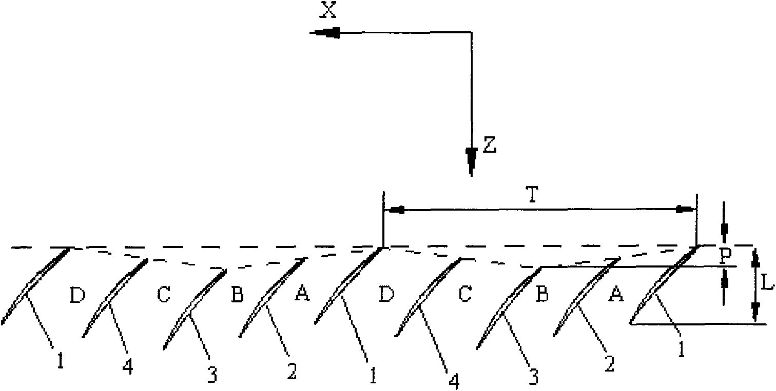
[0028] The arrangement of the blades in the rotating blade row in this embodiment is: N=2, in the circumferential direction X of the blade row, a blade group is formed by 5 adjacent blades, and the fifth blade is the next blade group. The first blade 1; in the same blade group, the second blade 2 is located on the side of the back surface of the first blade 1, the third blade 3 is located on the side of the back surface of the second blade 2, and the fourth One blade 4 is located on the side of the back surface of the third blade 3, the first blade 1 is located on the side of the back surface of the fourth blade 4 in the previous blade group, and so on. The position of the compressor axis Z of the leading edge of each blade in a blade group constitutes a triangular wave. The leading edge of the first blade 1 in the blade group is located at the peak of the triangular wave, and the leading edge of the third blade 3 is located at the trough of the triangular wave. , The period T ...
Embodiment 2
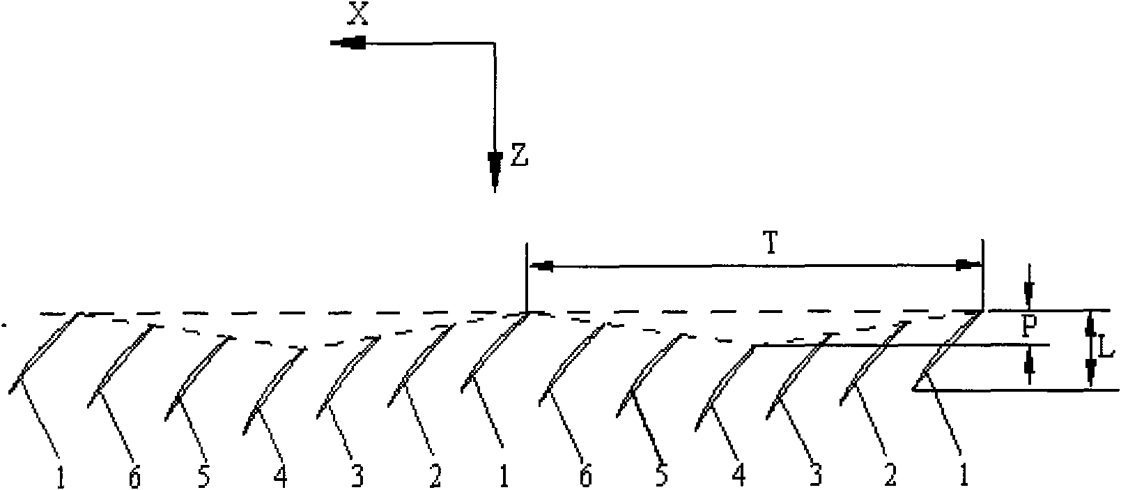
[0031] The arrangement of the blades in the row of rotating blades in this embodiment is: N=3, in the circumferential direction X of the blade row, 7 adjacent blades form a blade group, and the seventh blade is the next blade group. The first blade 1; in the same blade group, the second blade 2 is located on the side of the back surface of the first blade 1, the third blade 3 is located on the side of the back surface of the second blade 2, and the fourth One blade 4 is located on the side of the back surface of the third blade 3, the fifth blade 5 is located on the side of the back surface of the fourth blade 4, and the sixth blade 6 is located on the back surface of the fifth blade 5. Side, the first blade 1 is located on the side of the back surface of the fourth blade 6 in the previous blade group, and so on. The position of the compressor axis Z of the leading edge of each blade in a blade group constitutes a triangular wave. The leading edge of the first blade 1 in the bl...
Embodiment 3
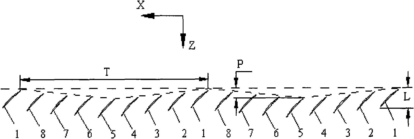
[0034] In this embodiment, the arrangement of the blades in the rotating blade row is: N=4, in the circumferential direction X of the blade row, a blade group is formed by 9 adjacent blades, and the ninth blade is the next blade group. The first blade 1. In the same blade group, the second blade 2 is located on the side of the back surface of the first blade 1, the third blade 3 is located on the side of the back surface of the second blade 2, and the fourth blade 4 is located on the Three blades 3 are on the back surface side of the blade, the fifth blade 5 is located on the back surface side of the fourth blade 4, the sixth blade 6 is located on the back surface side of the fifth blade 5, and the seventh blade The blade 7 is located on the side of the back surface of the sixth blade 6, the eighth blade 8 is located on the side of the back surface of the seventh blade 7, and the first blade 1 is located on the eighth blade 8 in the previous blade group. The back surface side ...
PUM
 Abstract
Description
Claims
Application Information
 - R&D
- Intellectual Property
- Life Sciences
- Materials
- Tech Scout
- Unparalleled Data Quality
- Higher Quality Content
- 60% Fewer Hallucinations
Browse by: Latest US Patents, China's latest patents, Technical Efficacy Thesaurus, Application Domain, Technology Topic, Popular Technical Reports.
© 2025 PatSnap. All rights reserved.Legal|Privacy policy|Modern Slavery Act Transparency Statement|Sitemap|About US| Contact US: help@patsnap.com


