Method for operating an internal combustion engine with parallel supercharging and with an activatable turbine, and internal combustion engine for carrying out a method of said type

a technology of internal combustion engine and activator, which is applied in the direction of combustion engine, machine/engine, electric control, etc., can solve the problems of reducing output power, affecting efficiency, and difficult configuration of exhaust-gas turbocharging, so as to improve torque characteristics, reduce engine speed range, and high charge pressure ratio

Active Publication Date: 2017-08-10
FORD GLOBAL TECH LLC
View PDF0 Cites 2 Cited by
  • Summary
  • Abstract
  • Description
  • Claims
  • Application Information

AI Technical Summary

Benefits of technology

[0016]In particular, with the exhaust-gas turbocharger which serves as a high-pressure stage, it is possible for the surge limit to be shifted in the direction of smaller compressor flows, as a result of which high charge pressure ratios can be obtained even with small compressor flows, which considerably improves the torque characteristic in the lower engine speed range. This is achieved by designing the high-pressure turbine for small exhaust-gas mass flows and by providing a bypass line by means of which, with increasing exhaust-gas mass flow, an increasing amount of exhaust gas is conducted past the high-pressure turbine. For this purpose, the bypass line branches off from the exhaust-gas discharge system upstream of the high-pressure turbine and opens into the exhaust-gas discharge system again upstream of the low-pressure turbine, wherein a shut-off element is arranged in the bypass line in order to control the exhaust-gas flow conducted past the high-pressure turbine. The response behavior of an internal combustion engine supercharged in this way is considerably improved in relation to a similar internal combustion engine with single-stage supercharging, because the relatively small high-pressure stage is less inert, that is to say the rotor of a smaller-dimensioned exhaust-gas turbocharger can be accelerated more rapidly.
[0017]The torque characteristic of a supercharged internal combustion engine may furthermore be improved by multiple turbochargers arranged in parallel, that is to say by multiple turbines of relatively small turbine cross section arranged in parallel, wherein turbines are activated successively with increasing exhaust-gas flow rate.

Problems solved by technology

While a mechanical charger extracts the energy required for driving it entirely from the internal combustion engine, and thereby reduces the output power and consequently adversely affects the efficiency, the exhaust-gas turbocharger utilizes the exhaust-gas energy of the hot exhaust gases.
The configuration of the exhaust-gas turbocharging often poses difficulties, wherein it is basically sought to obtain a noticeable performance increase in all rotational speed ranges.
According to previous systems, a severe torque drop is however observed in the event of a certain engine speed being undershot.
This has the result that, toward lower engine speeds, the charge pressure ratio and the charge pressure likewise decrease, which equates to a torque drop.
This approach has the disadvantage that the supercharging behavior is inadequate at relatively high rotational speeds or in the case of relatively high exhaust-gas quantities.
However, the inventors herein have recognized an issue with the above approaches.
The response behavior is thus impaired.
Specifically, if the rotational speed of the charger shaft falls below a minimum rotational speed, or if the charger shaft even comes to a standstill, the seal of the bearing arrangement of the oil-lubricated charger shaft can leak at the compressor side.
If oil passes via the associated compressor into the intake system, the oil-contaminated fresh charge supplied to the cylinders adversely affects the combustion process, whereby, in particular, the untreated particle emissions can greatly increase.
The oil may also be deposited on the inner walls of the intake system and impair the flow conditions in the intake system and / or in the compressor, and contaminate a charge-air cooler arranged downstream.
Firstly, the labyrinth seal that is generally used in the case of charger shafts appears to provide a satisfactory sealing action only when the charge shaft is at a certain minimum rotational speed.
Secondly, when the turbine is deactivated, or when the compressor is not being driven, it is generally the case that a negative pressure prevails at the compressor-side end of the bearing arrangement, which negative pressure sucks or pulls the oil out of the bearing and into the intake system downstream of the non-driven compressor.

Method used


Image

  • Method for operating an internal combustion engine with parallel supercharging and with an activatable turbine, and internal combustion engine for carrying out a method of said type
  • Method for operating an internal combustion engine with parallel supercharging and with an activatable turbine, and internal combustion engine for carrying out a method of said type
  • Method for operating an internal combustion engine with parallel supercharging and with an activatable turbine, and internal combustion engine for carrying out a method of said type

Examples


first embodiment

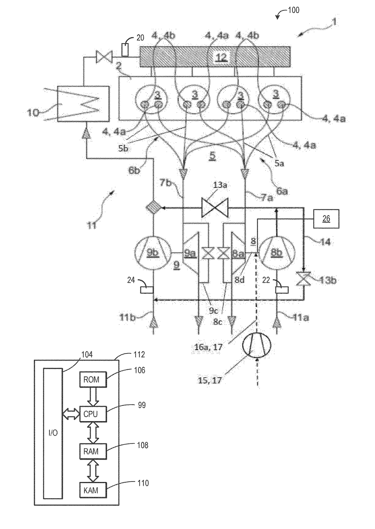
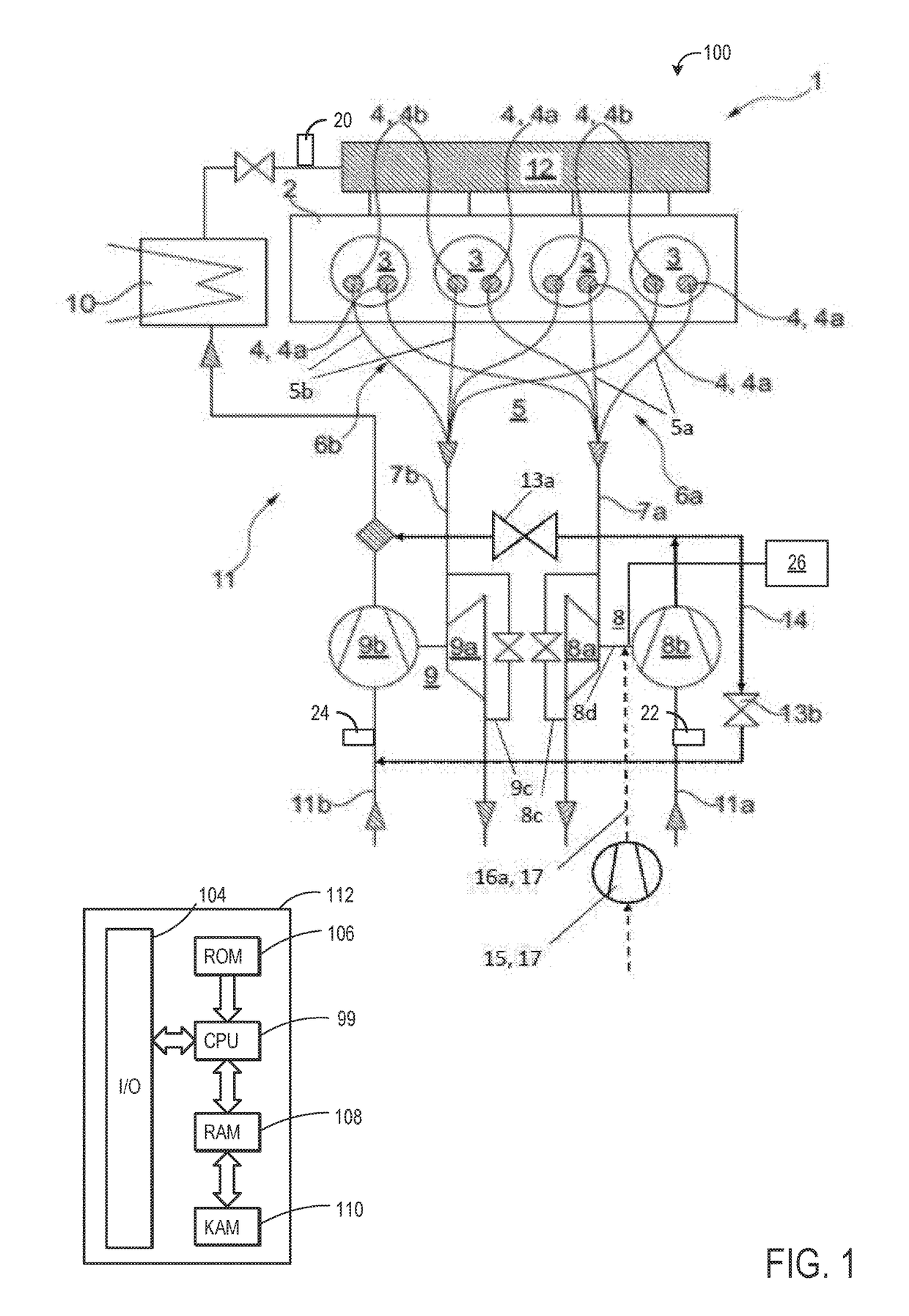
[0089]FIG. 1 schematically shows an engine system 100 including the supercharged internal combustion engine 1 which is equipped with two exhaust-gas turbochargers 8, 9. Each exhaust-gas turbocharger 8, 9 comprises a turbine 8a, 9a and a compressor 8b, 9b which are arranged on the same shaft 8d, which shaft is mounted rotatably in an oil-lubricated bearing arrangement. The hot exhaust gas expands in the turbines 8a, 9a with a release of energy. The compressors 8b, 9b compress the charge air which is supplied to the cylinders 3 via intake system 11, charge-air cooler 10 and plenum 12, as a result of which supercharging of the internal combustion engine 1 is realized.

[0090]Said internal combustion engine is a four-cylinder in-line engine 1 in which the four cylinders 3 are arranged along the longitudinal axis of the cylinder head 2, that is to say in a line. Each cylinder 3 has two outlet openings 4 (a first outlet opening 4a and a second outlet opening 4b) which are adjoined by exhaus...

second embodiment

[0102]FIG. 2 schematically shows an engine system 200 including the supercharged internal combustion engine 1. It is sought to explain only the differences in relation to the embodiment illustrated in FIG. 1, for which reason reference is otherwise made to FIG. 1. The same reference signs have been used for the same components.

[0103]In the present case, too, auxiliary mechanism 17 for increasing the pressure on the compressor-side end of the bearing arrangement of the shaft 8d of the first exhaust-gas turbocharger 8 is provided. In addition to the pump 15 illustrated in FIG. 1, which subjects the bearing seal to the action of compressed air at the compressor side via the first feed line 16a, a second feed line 16b is provided which branches off from the intake system 11 downstream of the second compressor 9b and which provides charge air which serves as compressed air. Then, the pressure at the compressor-side end of the bearing arrangement of the shaft 8b is increased also using th...


PUM


Abstract

Embodiments for an engine coupled to a first turbocharger and a second turbocharger are provided. One example includes responsive to a first condition, deactivating a first turbine of the first turbocharger and meeting a boost demand via operation of the second turbocharger, and responsive to deactivating the first turbine, increasing a pressure at a compressor-side end of a bearing arrangement of a shaft of the first turbocharger. In this way, oil leakage from the bearing arrangement may be reduced.

Description

CROSS REFERENCE TO RELATED APPLICATIONS[0001]This application claims priority to German Patent Application No. 102016201729.2, filed on Feb. 4, 2016. The entire contents of the above-referenced application are hereby incorporated by reference in its entirety for all purposes.FIELD[0002]The disclosure relates to a method for operating a supercharged internal combustion engine.BACKGROUND AND SUMMARY[0003]Internal combustion engines may include a cylinder block and at least one cylinder head which are connected to one another at an assembly end side to form the cylinders. To control the charge exchange, an internal combustion engine may utilize control elements—generally in the form of lifting valves—and actuating devices for actuating these control elements. Each lifting valve moves, so as to realize, that is to say perform, a valve lift, between an open position and a closed position, and in so doing, during an opening duration, opens up the opening associated with the valve. The val...

Claims


Application Information

Patent Timeline
Patent Type & Authority Applications(United States)
IPC IPC(8): F02B37/16F02D23/00F02B37/007
CPCF02B37/16F02D23/00F02B37/007F02B37/12F02B39/16F02B37/001F02D13/0257F02D41/0007Y02T10/12
Inventor STOFFELS, HARALDSTUMP, LUDWIGGRIESER, KLEMENSWOJAHN, JENSBRINKMANN, FRANZ J.
Owner FORD GLOBAL TECH LLC
Why Eureka
Try Eureka