Speed change apparatus for vehicle

a technology for changing apparatuses and vehicles, applied in the direction of gearing details, transportation and packaging, gearing, etc., can solve the problems of reducing the rotational speed, the rotational speed, and the corresponding increase in the rotational speed, so as to reduce the impact sound and enhance the return torque of the shift spindle.

Active Publication Date: 2016-10-06
HONDA MOTOR CO LTD
View PDF0 Cites 4 Cited by
  • Summary
  • Abstract
  • Description
  • Claims
  • Application Information

AI Technical Summary

Benefits of technology

[0012]The present invention has been made in consideration of the problems in the related art. Accordingly, it is an object of the present invention to make it possible to enhance

Problems solved by technology

Therefore, the shift fork cannot move the shifter gear.
A problem to be solved relates to a return torque of a shift spindle and a torque which is applied to a shift drum by a master arm.
An increase in TMA′ leads to a corresponding increase in the rotational spe

Method used


Image

  • Speed change apparatus for vehicle
  • Speed change apparatus for vehicle
  • Speed change apparatus for vehicle

Examples


Embodiment Construction

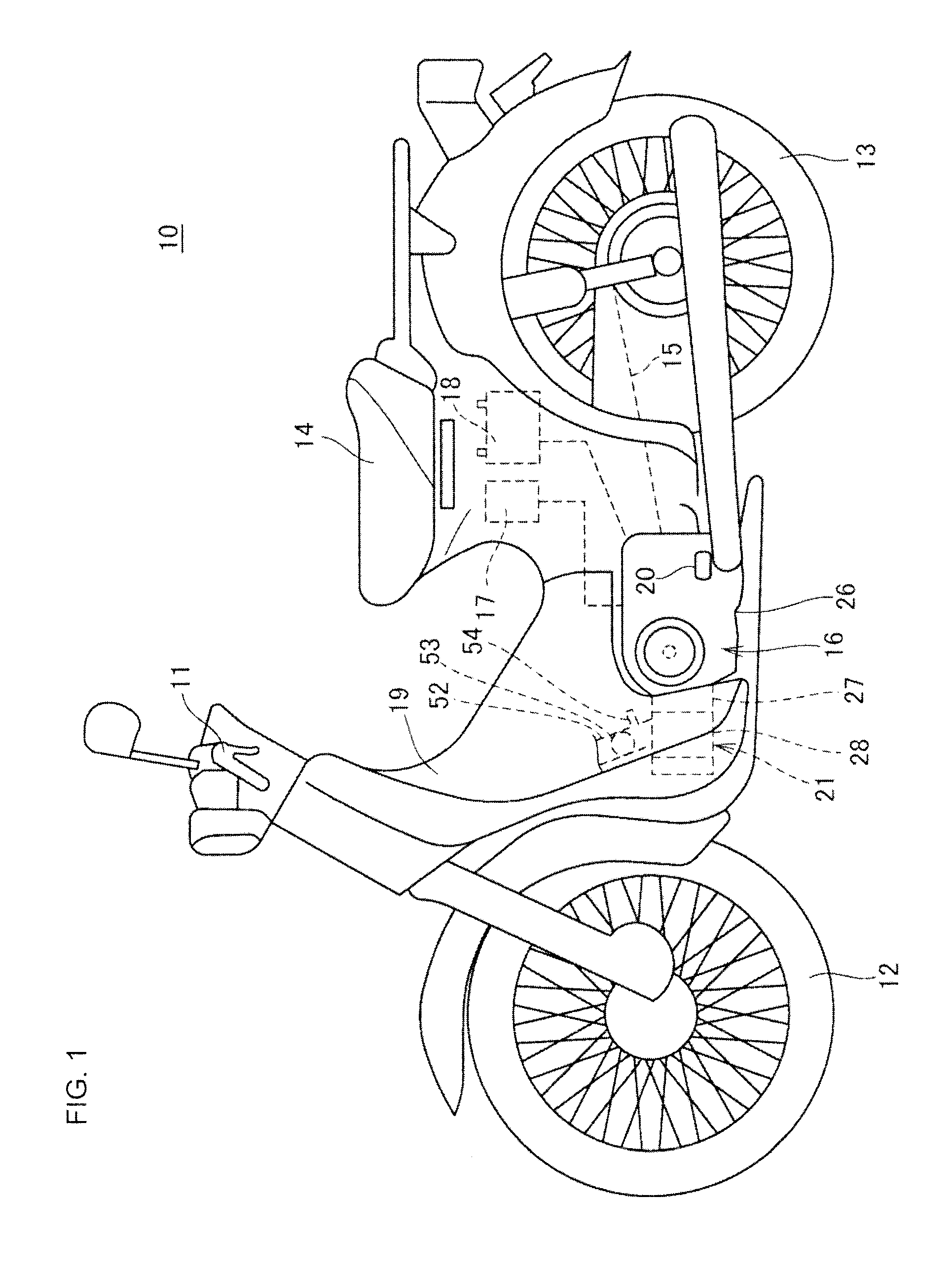
[0044]FIG. 1 is a left side view of a motorcycle 10 provided with an automatic speed change apparatus 25 according to an embodiment of the present invention.

[0045]The motorcycle 10 includes a handlebar 11 rotatably supported on a head pipe (not shown), a front wheel 12 steered by the handlebar 11, a rear wheel 13 as a driving wheel, a seat 14 on which to seat a driver, a power unit 16 configured to supply a driving force to the rear wheel 13 through a chain 15, a control unit 17 (speed change controller) configured to control the power unit 16, and a battery 18.

[0046]The motorcycle 10 is configured based on a body frame (not shown), and the body frame is covered with a body cover 19. The control unit 17 and the battery 18 are disposed under the seat 14 and inside the body cover 19. The power unit 16 is provided at a roughly middle position between the front wheel 12 and the rear wheel 13, downwardly and slightly forwardly of the seat 14. A pair of left and right driver footrests 20 ...


PUM


Abstract

A speed change apparatus includes a transmission, a change mechanism configured to move a gear or gears so as to change gear position, a force accumulation mechanism which includes a shift spindle and a force accumulation spring. The shift spindle is provided, in a rotatable manner, with a master arm configured to operate the change mechanism. A return spring is configured to bias the master arm toward a neutral position. A sub return spring, separate from the return spring and which directly biases the shift spindle toward the neutral position, is provided between the shift spindle and a case member.

Description

BACKGROUND[0001]1. Field[0002]The present invention relates to a speed change apparatus for a vehicle.[0003]2. Description of the Related Art[0004]Conventionally, in relation to a transmission for a motorcycle provided with an AMT (automated manual transmission) transmission, there has been disclosed a peripheral structure for a shift spindle (see, for example, PCT Patent Publication No. WO 2014 / 157631 (Patent Document 1)). Specifically, the shift spindle in the document is of a so-called interlocked spindle type provided with both a clutch lever for operating a clutch and a master arm for operating a change mechanism of the transmission. Besides, a force accumulation mechanism is provided between the shift spindle and the master arm. Here, the shift spindle is driven by a shift motor.[0005]The change mechanism includes the master arm, a shift drum rotated by the master arm, and a shift fork which is driven by the shift drum and moves in an axial direction a shifter gear constitutin...

Claims


Application Information

Patent Timeline
IPC IPC(8): F16H3/20F16H57/02F16H63/08
CPCF16H3/20F16H57/02F16H63/08F16H3/30F16H63/18F16H2057/0203F16H2057/02065F16H2200/0043
Inventor ADACHI, JUNONO, JUNYA
Owner HONDA MOTOR CO LTD
Why Eureka
Try Eureka