Supercharge Your Innovation With Domain-Expert AI Agents!

LED illumination device

A technology of LED lighting and LED chips, which is applied to lighting devices, components of lighting devices, lighting and heating equipment, etc., can solve problems such as chromaticity changes, and achieve the effect of reducing the possibility of color unevenness

Inactive Publication Date: 2012-04-11
MATSUSHITA ELECTRIC WORKS LTD
View PDF1 Cites 0 Cited by
  • Summary
  • Abstract
  • Description
  • Claims
  • Application Information

AI Technical Summary

Problems solved by technology

Therefore, it is likely that chromaticity changes will occur

Method used


Image

  • LED illumination device
  • LED illumination device
  • LED illumination device

Examples


Embodiment Construction

[0029] Embodiments of the present invention will be described in detail below with reference to the accompanying drawings that constitute a part of the present invention.

[0030] will now refer to Figures 1 to 3B An LED lighting device according to a first embodiment of the present invention will be described.

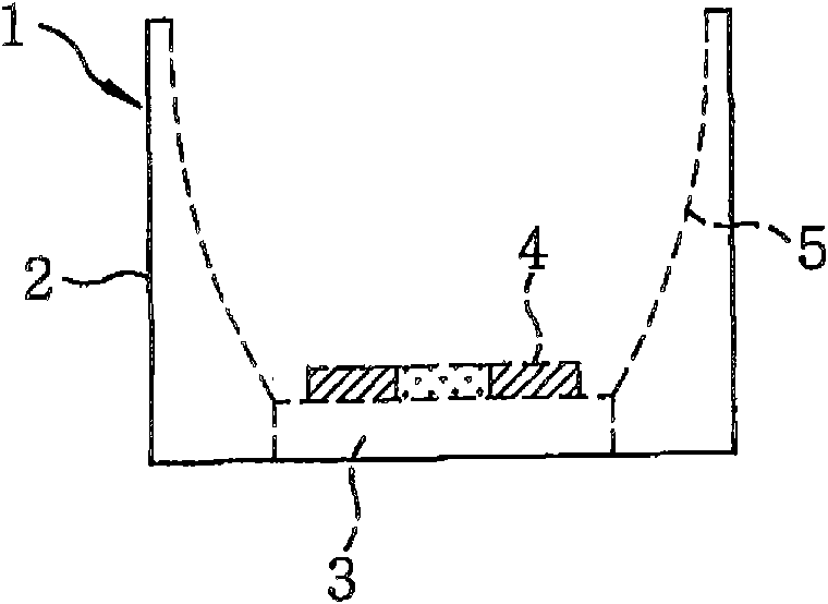
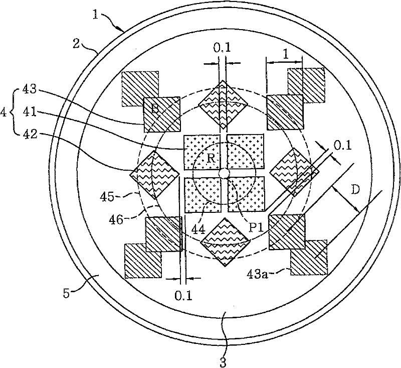
[0031] refer to figure 1 and figure 2 , The LED lighting device 1 according to the present embodiment includes a generally cylindrical main body 2 made of resin or metal material, and a substrate 3 provided on the bottom of the main body 2 and formed of a printed board or the like. The LED lighting device 1 also includes a plurality of LED chips 4 disposed on a substrate 3, and a reflection plate 5 disposed inside the main body 2 for reflecting light emitted from the LED chips 4 to the outside.

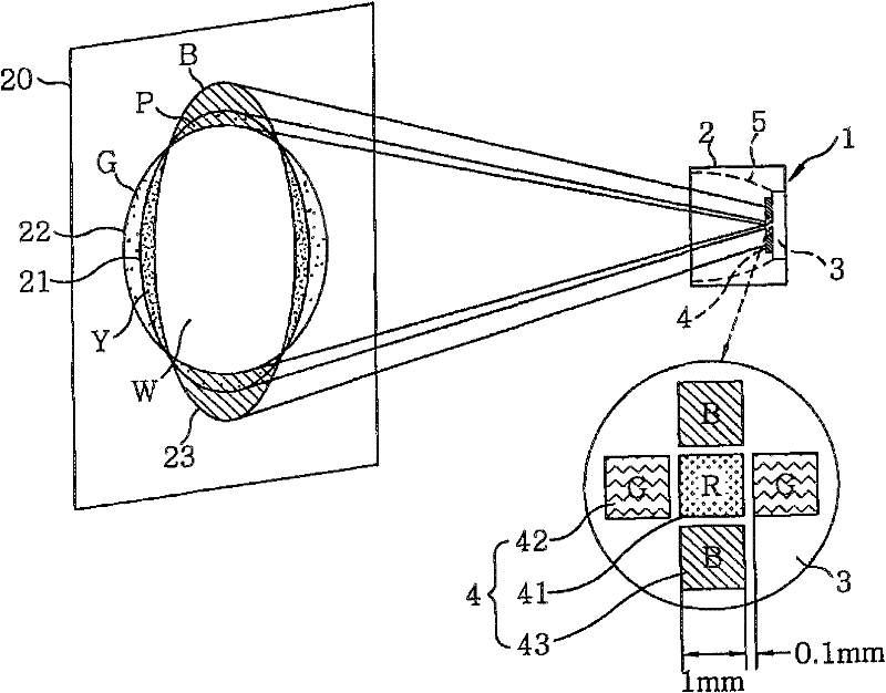
[0032] The LED lighting device 1 according to the present embodiment is designed paying attention to the color of the peripheral portion of the radiation pattern and the...


PUM


Abstract

An LED illumination device includes: a substrate; one or more red LED chips arranged on the substrate; a plurality of blue LED chips arranged on the substrate; and a plurality of third-color LED chips arranged on the substrate. Respective centers of the red LED chips are arranged on a circumference of a first circle having as its center a point on the substrate, respective centers of the blue LEDchips being arranged on the circumference of a second circle concentric with and greater than the first circle, respective centers of the third-color LED chips being arranged in a region between the first circle and the second circle.

Description

technical field [0001] The invention relates to an LED lighting device capable of obtaining different lighting colors through additional color mixing, wherein red, green and blue single-color LED chips are used in combination. Background technique [0002] Conventionally, there is known an LED lighting device in which the light-emitting centers of single-color LED chips of three primary colors are aligned to obtain, for example, white radiant light. In this LED lighting device, a single red LED chip is placed in the center of the substrate, while a plurality of green LED chips and a plurality of blue LED chips are arranged so that the same blue or green LED chip is symmetrical with respect to the center of the substrate ( For example, see JP Utility Model No. 6-79165A). [0003] In this LED lighting device, considering the fact that LED chips of different colors are used as light-emitting points of the display device mainly as planar light sources, and paying attention to t...

Claims


Application Information

Patent Timeline
Patent Type & Authority Patents(China)
IPC IPC(8): F21S10/02F21V7/10F21V5/04F21V3/00
CPCF21Y2105/003H01L2924/0002H01L33/54H01L25/0753F21Y2113/005F21K9/00F21Y2101/02F21Y2105/12F21Y2105/10F21Y2115/10F21Y2113/13H01L2924/00
Inventor 白川友树松林容子
Owner MATSUSHITA ELECTRIC WORKS LTD
Features
  • R&D
  • Intellectual Property
  • Life Sciences
  • Materials
  • Tech Scout
  • Unparalleled Data Quality
  • Higher Quality Content
  • 60% Fewer Hallucinations
Learn More