
Cascading type fiber laser

A fiber laser, cascade technology, used in lasers, laser parts, phonon exciters, etc., can solve the problems of unstable output power, large signal loss, damage, etc., and achieve the effect of reducing instantaneous high

Inactive Publication Date: 2012-07-18
深圳市欧凌镭射科技有限公司
View PDF0 Cites 0 Cited by
  • Summary
  • Abstract
  • Description
  • Claims
  • Application Information

AI Technical Summary

Problems solved by technology

Side-pumping technologies include V-groove side-pumping, micro-prism side-coupling pumping, and fiber-optic side-gluing pumping, etc., and their coupling efficiencies are all less than 90%, and the processing technology is very complicated and the cost is high.
End pumping technology includes direct lens end coupling, fiber end fusion coupling pumping, etc. The lens end coupling technology is limited by the optical parameters of the fiber and the technical parameters of the lens components, etc., resulting in low pumping efficiency, unstable system, and high cost.
Optical fiber end-face fusion coupling pumping technology is an ITF patent. This technology has high requirements for optical fiber fusion drawing technology. Some domestic research institutions have conducted research on it, but have not yet mastered it.
Second, after the pump light completes the pumping process, the relative pump residual energy will be considerable. How to take away the residual light in the optical fiber so that it will not burn the optical fiber and optical devices? Generally, the residual cladding pump light is very easy to cause optical damage to the optical fiber and optical devices in the optical path, resulting in unstable output power
The manufacturing process of this type of multi-port beam combiner is particularly complicated, and it is very difficult to draw. Even the finished product has low pump coupling efficiency and large signal loss.
Although many scientific research institutions and companies at home and abroad have developed it and made some progress, they still have not been able to produce ideal and practical products.

Method used


Image

  • Cascading type fiber laser
  • Cascading type fiber laser
  • Cascading type fiber laser

Examples


Embodiment Construction

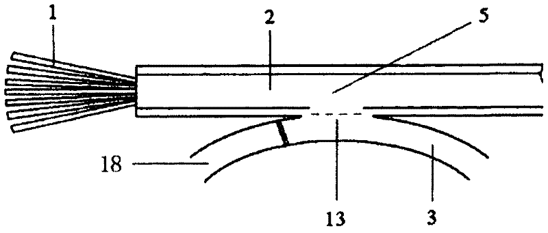
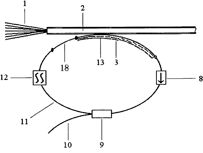
[0024] Preferred examples of the present invention, such as image 3 , Figure 4 As shown, a cascaded fiber laser includes an optical resonant cavity, 7 (other numbers can also be used) pump input fibers 1, pump output fibers 2, the 7 pump input fibers 1 and a pump 7 × 1 fiber bundle combiner (such as figure 1 shown), also includes an active double-clad fiber 3, the active double-clad fiber 3 is coupled with the side of the pump output fiber 2 to form a (1+1)×1 fiber combiner 5 (such as figure 2 shown), the optical resonator is composed of the active double-clad fiber 3 of the (1+1)×1 fiber combiner 5, an optical isolator 8, an optical coupler 9 and a narrowband optical filter 12 ring-structured optical resonators connected sequentially (such as image 3 shown), the optical coupler 9 separates a small output end 11 and a large output end 10, the small output end 11 is connected to the input end of the narrowband optical filter 12 by welding, and the large output end 10 is ...


PUM


Abstract

The invention discloses a cascading type fiber laser comprising an optical resonant cavity, a plurality of pump input fibers, pump output fibers, n*1 fiber combiners formed by coupling the pump input fibers and the pump output fibers and (1+1)*1 fiber combiners formed by coupling and connecting an active double-clad fiber and the side faces of the pump output fibers, wherein the optical resonant cavity is formed by sequentially connecting the active double-clad fiber, an optical isolator, an optical coupler and a narrow-band optical filter of the (1+1)*1 fiber combiners and has a ring structure, the optical coupler is divided into a small output end and a big output end, the small output end is fused and connected with the input end of the narrow-band optical filter, and the big output end is fused with the cascaded fiber combiner groups on the pump output fibers. A plurality of fiber combiner groups connected in series together can evenly and fully absorb pump light energy step by step and decrease the unstable influence caused by instantaneous overhigh pump light power or power drift in a high-power pump to the laser output power.

Description

technical field [0001] The invention relates to a fiber laser, in particular to a high-power output cascaded fiber laser. Background technique [0002] Fiber laser is known as an emerging technology in the laser field. It has broad application prospects in many fields. In recent years, it has become a hot research topic in the world. Its rapid development and wide application have attracted great attention. Among them, high-power double-clad fiber lasers are even more prominent. Based on double-clad fibers and represented by multi-mode cladding pumping technology, the conversion efficiency and output power of fiber lasers are greatly improved, and the beam quality is basically close to that of at the diffraction limit. [0003] To achieve high power output of double-clad fiber lasers, effective pumping technology becomes the key. The existing technology is generally realized by continuously increasing the energy of the pump light injected into the active fiber, but once th...

Claims


Application Information

Patent Timeline
Patent Type & Authority Patents(China)
IPC IPC(8): H01S3/067H01S3/094
Inventor 杨昌盛董杰
Owner 深圳市欧凌镭射科技有限公司
Learn More