Y-Sb-based composite magnetic particle optical catalyst in nuclear shell structures and application

A technology of shell structure and structural formula is applied to a core-shell structure yttrium-antimony-based composite magnetic particle photocatalyst and its application field, and can solve the problems of low photocatalytic efficiency, high photocatalytic efficiency, and low utilization rate of sunlight.

Active Publication Date: 2013-02-13
NANJING UNIV
View PDF0 Cites 0 Cited by
  • Summary
  • Abstract
  • Description
  • Claims
  • Application Information

AI Technical Summary

Problems solved by technology

However, photocatalytic technology has not been industrialized in water treatment and wastewater treatment, and there are two main problems: (1) The photocatalytic efficiency of the suspension system photocatalytic system is high, and there is a problem of post-treatment of the catalyst. If the photocatalyst is fixed on glass and other materials It can solve the problem of separation and recovery of photocatalyst, but its photocatalytic efficiency is significantly lower than that of the suspension system; (2) titanium dioxide can only absorb ultraviolet light, has no response in the visible light range, and has a low utilization rate of sunlight (4%), while The ultraviolet part of the solar spectrum only accounts for less than 5%, while the visible light with a wavelength of 400-750nm accounts for 43% of the solar spectrum. If the ultraviolet and visible light bands in sunlight can be fully utilized at the same time, the photon quantum efficiency will increase will be greatly improved

Method used


Image

  • Y-Sb-based composite magnetic particle optical catalyst in nuclear shell structures and application
  • Y-Sb-based composite magnetic particle optical catalyst in nuclear shell structures and application
  • Y-Sb-based composite magnetic particle optical catalyst in nuclear shell structures and application

Examples


specific Embodiment approach

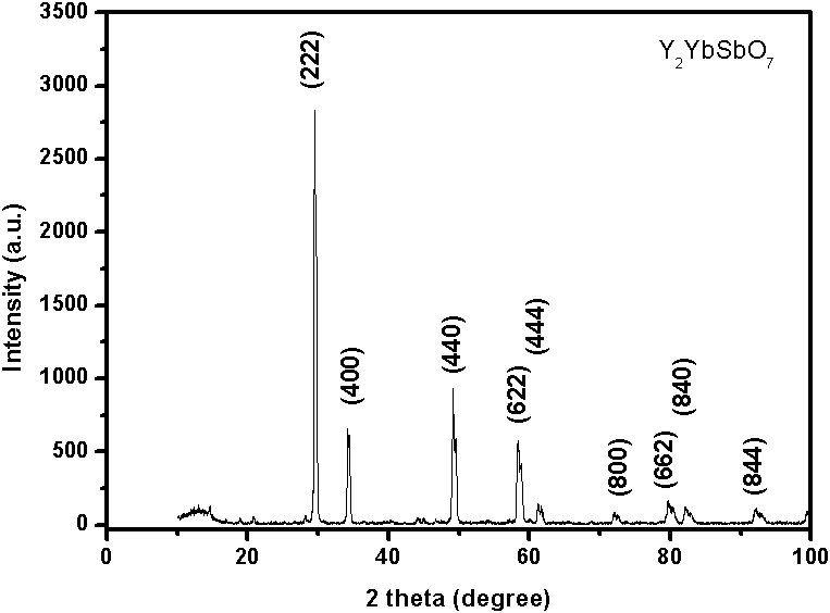
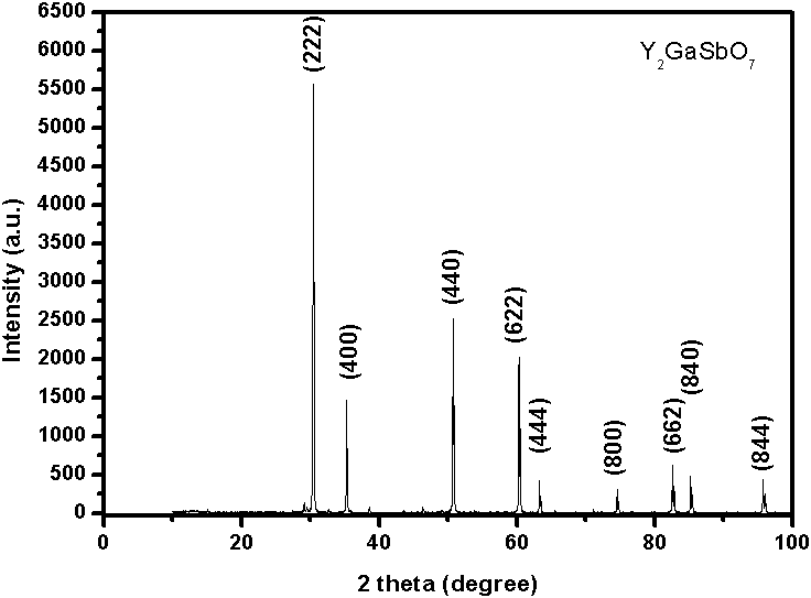
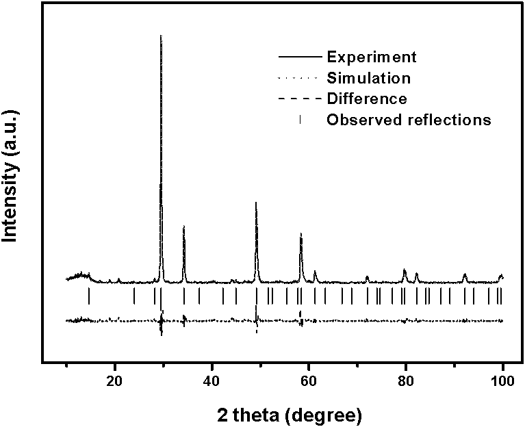
[0043] 1. Powder catalytic material Y 3-x Yb x SbO 7 (0.5≤x≤1) and Y 3-x Ga x SbO 7 (0.5≤x≤1) preparation process route is as follows:

[0044] (1) Powder catalytic material Y 3-x Yb x SbO 7 Preparation of (0.5≤x≤1): Y is prepared by high-temperature solid-state sintering 3-x Yb x SbO 7 (0.5≤x≤1) photocatalytic powder material. Y with a purity of 99.99% 2 o 3 , Yb 2 o 3 and Sb 2 o 5 As a raw material, Y, Yb, Sb are Y in the atomic ratio of the molecular formula 2 o 3 , Yb 2 o 3 and Sb 2 o 5 Mix thoroughly, then grind in a ball mill, the particle size of the powder reaches 1.4-1.8 microns, dry at 200±40°C for 4±1 hours, press into tablets, and put them into a high-temperature sintering furnace for firing. Raise the temperature of the furnace to 700±20°C, keep it warm for 8±2 hours, then cool down with the furnace, take out the pressed powder and crush it to a particle size of 1.3-1.6 microns, then press the powder into a tablet, put it into a high-tempera...


PUM

PropertyMeasurementUnit
particle diameteraaaaaaaaaa
diameteraaaaaaaaaa

Abstract

The invention relates to a catalytic material in nuclear shell structures, which is shown in the following structural formulas: gama-Fe2O3-Y3-xYbxSbO7 (x is not less than 0.5 and is not more than 1), gama-Fe2O3-Y3-xGaxSbO7 (x is not less than 0.5 and is not more than 1), SiO2- Y3-xYbxSbO7 (x is not less than 0.5 and is not more than 1), SiO2- Y3-xGaxSbO7 (x is not less than 0.5 and is not more than 1), MnO2-Y3-xYbxSbO7 (x is not less than 0.5 and is not more than 1) or MnO2-Y3-xGaxSbO7 (x is not less than 0.5 and is not more than 1). The particle diameters of the gama-Fe2O3, the SiO2 and the MnO2 are 0.06-2 micros and are 0.07-2.1 micros after magnetic particles are coated by the Y3-xYbxSbO7 (x is not less than 0.5 and is not more than 1) and the Y3-xGaxSbO7 (x is not less than 0.5 and is not more than 1) which are used as a catalytic material. Sewage is degraded by a reaction system including a magnetic field device and the optical catalytic material in three nuclear shell structures in an aqueous solution under the conditions that the magnetic field strength is 0.3-0.6 T, a xenon lamp or a high-pressure mercury lamp is used as a light source, and the whole illumination reaction is carried out in a sealed light-tight environment.

Description

technical field [0001] The present invention relates to a novel photocatalyst, preparation and application, especially powder catalytic material Y 3-x Yb x SbO 7 (0.5≤x≤1), Y 3-x Ga x SbO 7 (0.5≤x≤1) and γ-Fe with "magnetic particle core-photocatalyst shell" structure 2 o 3 (Ferromagnetic particle core)-Y 3-x Yb x SbO 7 (0.5≤x≤1) (photocatalyst shell), γ-Fe 2 o 3 -Y 3-x Ga x SbO 7 (0.5≤x≤1) (photocatalyst shell), SiO 2 (paramagnetic particle core)-Y 3-x Yb x SbO 7 (0.5≤x≤1), SiO 2 -Y 3-x Ga x SbO 7 (0.5≤x≤1), MnO (antiferromagnetic particle core)-Y 3-x Yb x SbO 7 (0.5≤x≤1), MnO-Y 3-x Ga x SbO 7 (0.5≤x≤1), the application of photocatalytic removal of organic pollutants in water, and the application of photocatalytic decomposition of water to produce hydrogen. Background technique [0002] The treatment of toxic and refractory organic substances (PTS) in water has always been a difficult and hot topic in the field of water treatment. PTS has the ch...

Claims


Application Information

Patent Timeline
Patent Type & Authority Patents(China)
IPC IPC(8): B01J23/843B01J23/18B01J23/34B01J23/644C02F1/30C02F1/32C02F1/48C01B3/04C02F101/38C02F101/36
CPCY02E60/364Y02E60/36Y02W10/37
Inventor 栾景飞马坤胡知田张玲燕
Owner NANJING UNIV
Why Eureka
Try Eureka