Bearing injection mold

A technology for injection molds and bearings, which is applied to household appliances, other household appliances, household components, etc. It can solve the problems of point B gap, entry into the interior of bearing 3, failure, etc., and achieve the effect of reliable mold work

Inactive Publication Date: 2013-06-26
WUXI NO 2 BEARING
View PDF0 Cites 0 Cited by
  • Summary
  • Abstract
  • Description
  • Claims
  • Application Information

AI Technical Summary

Problems solved by technology

It is impossible to ensure that the three points A, B, and C can be positioned closely at the same time during mold processing. If there is a gap at point B after the upper mold 1 and the lower mold 4 are closed, the mold that enters the mold cavity from the injection

Method used


Image

  • Bearing injection mold
  • Bearing injection mold

Examples


Embodiment Construction

[0011] The specific embodiments of the present invention will be further described below in conjunction with the accompanying drawings.

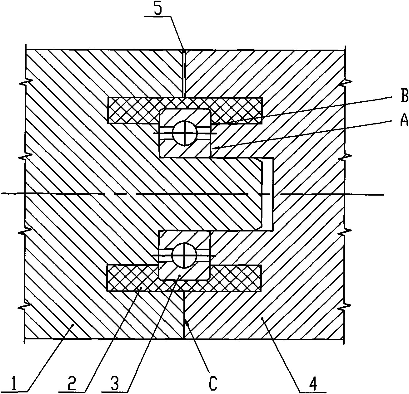
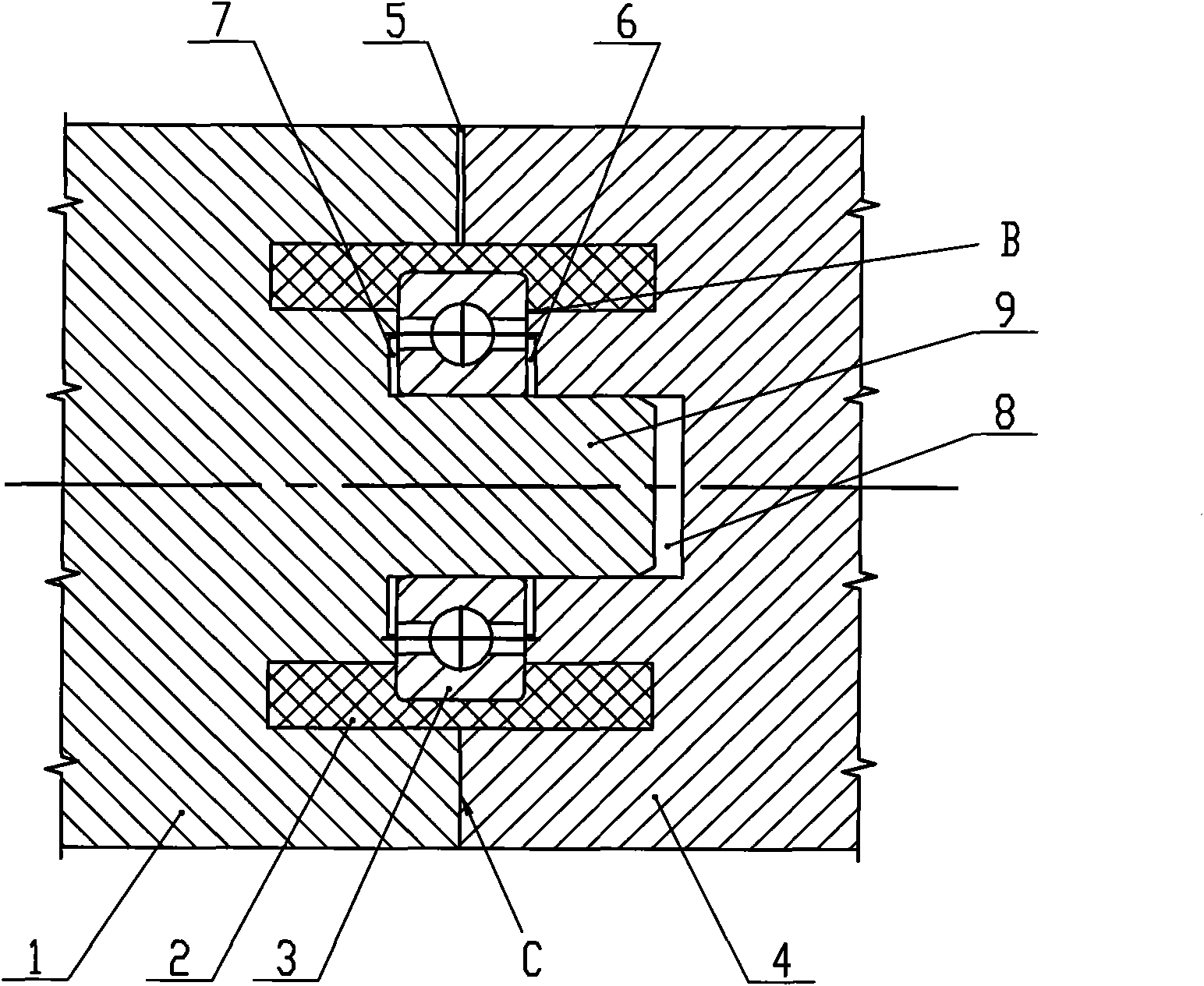
[0012] like figure 2 As shown, the present invention is a bearing injection mold, comprising an upper mold 1 and a lower mold 4, the upper mold 1 is provided with a positioning shaft 9, the lower mold 4 is provided with a positioning hole 8, and the positioning shaft 9 is matched with the positioning hole 8 . A mold cavity is formed between the upper mold 1 and the lower mold 4 , and an injection port 5 communicating with the mold cavity is arranged between the upper mold 1 and the lower mold 4 .

[0013] A first groove 7 is arranged on the upper mold 1 corresponding to the inner ring of the bearing 3 , and the width of the first groove 7 is larger than that of the inner ring of the bearing 3 . A second groove 6 may also be provided on the lower mold 4 corresponding to the inner ring of the bearing 3 , and the width of the second groove 6...


PUM


Abstract

The invention relates to a bearing injection mold, which comprises an upper mold and a lower mold. A mold cavity is formed between the upper mold and the lower mold; an injection opening which is communicated with the cavity is formed between the upper mold and the lower mold; a first groove is formed on the upper mold corresponding to a bearing inner ring; and the width of the first groove is greater than that of the bearing inner ring. The bearing injection mold cancels an over-positioning point in the prior art. Therefore, a gap is formed between the bearing inner ring and the mold; the positioning point between a bearing outer ring and the mold is guaranteed; the problem that the plastic enters the interior of the bearing during injection molding is solved; and the work of the mold isreliable.

Description

technical field [0001] The invention relates to a bearing injection mold, in particular to a mold for pouring a layer of plastic parts on the bearing outer ring. Background technique [0002] The bearing injection mold is used to cast a layer of plastic parts on the outer ring of the bearing to make the bearing into a wheel. like figure 1 As shown, the existing bearing injection mold includes an upper mold 1 and a lower mold 4 , and the bearing 3 is placed in a cavity formed by the upper mold 1 and the lower mold 4 . The mold has three positioning points for positioning: point A, the inner ring of the bearing 3 is close to the upper mold 1 and the lower mold 4; point B, the outer ring of the bearing 3 is close to the upper mold 1 and the lower mold 4; point C, In order to ensure the total thickness of the wheel (ie the plastic part 2), the upper mold 1 and the lower mold 4 are close at point C again. It is impossible to ensure that the three points A, B, and C can be posi...

Claims


Application Information

Patent Timeline
IPC IPC(8): B29C45/26B29C45/14B29L31/04
Inventor 谭义银
Owner WUXI NO 2 BEARING
Why Eureka
Try Eureka