
Internalized charging method for standby lead-acid battery

A lead-acid battery, charging method technology, applied in the direction of secondary battery charging/discharging, secondary battery repair/maintenance, etc., to achieve the effect of high cycle life

Active Publication Date: 2010-10-06
ZHEJIANG TIANNENG BATTERY JIANGSU +3
View PDF3 Cites 23 Cited by
  • Summary
  • Abstract
  • Description
  • Claims
  • Application Information

AI Technical Summary

Problems solved by technology

[0004] This method starts from the service life requirements of the product and takes into account the initial capacity requirements of the battery. The problems to be solved are: 1. The temperature control during the charging process to avoid micro-short circuits caused by excessive battery temperature; The capacity is not less than 100%, and there is no waste of electricity; 3. Fully consider the crystal structure of the active material to prolong the cycle life of the battery

Method used


Image

  • Internalized charging method for standby lead-acid battery

Examples


Embodiment 1

[0013] A backup lead-acid storage battery internalization charging method, comprising the following steps: the storage battery filled with acid is placed in a circulating water bath for 5 minutes, the internal temperature of the battery is reduced to below 40°C, and the charging circuit of the storage battery is connected to prepare for charging. When the battery temperature is not higher than 40°C, turn on the charger for charging, specifically:

[0014] (1) at 0.03C 10 Charge for 5 hours; (2) then charge at 0.1C 10 Charge for 33 hours; (3) then charge at 0.06C 10 Charge for 12 hours; (4) then charge at 0.1C 10 Discharge for 7 hours; (5) then use 0.1C 10 Charge for 10 hours; (6) then charge at 0.05C 10 Charge for 9 hours; then, (7) stand still for 0.5 hours; (8) charge at 0.1C 10 Discharge for 8 hours; (9) then use 0.1C 10 Charge for 9 hours; (10) then charge at 0.06C 10 Charge for 5 hours.

[0015] During the charging process, pay attention to controlling the battery...

Embodiment 2

[0017] specifically is:

[0018] (1) at 0.04C 10 Charge for 5 hours; (2) then charge at 0.15C 10 Charge for 32 hours; (3) then charge at 0.07C 10 Charge for 11 hours; (4) then charge at 0.11C 10 Discharge for 8 hours; (5) then at 0.11C 10 Charge for 11 hours; (6) then charge at 0.07C 10 Charge for 10 hours; then, (7) stand still for 0.7 hours; (8) charge at 0.11C 10 Discharge for 9 hours; (9) and then at 0.11C 10 Charge for 8 hours; (10) then charge at 0.07C 10 Charge for 5 hours.

[0019] All the other implementations are as in Example 1.

Embodiment 3

[0021] specifically is:

[0022] (1) at 0.05C 10 Charge for 5 hours; (2) then charge at 0.15C 10 Charge for 31 hours; (3) then charge at 0.08C 10 Charge for 11 hours; (4) then charge at 0.12C 10 Discharge for 8 hours; (5) then at 0.12C 10 Charge for 10 hours; (6) then charge at 0.08C 10 Charge for 10 hours; then, (7) stand still for 0.6 hours; (8) recharge at 0.12C 10 Discharge for 10 hours; (9) then at 0.12C 10 Charge for 10 hours; (10) then charge at 0.08C 10 Charge for 5 hours.

[0023] All the other implementations are as in Example 1.

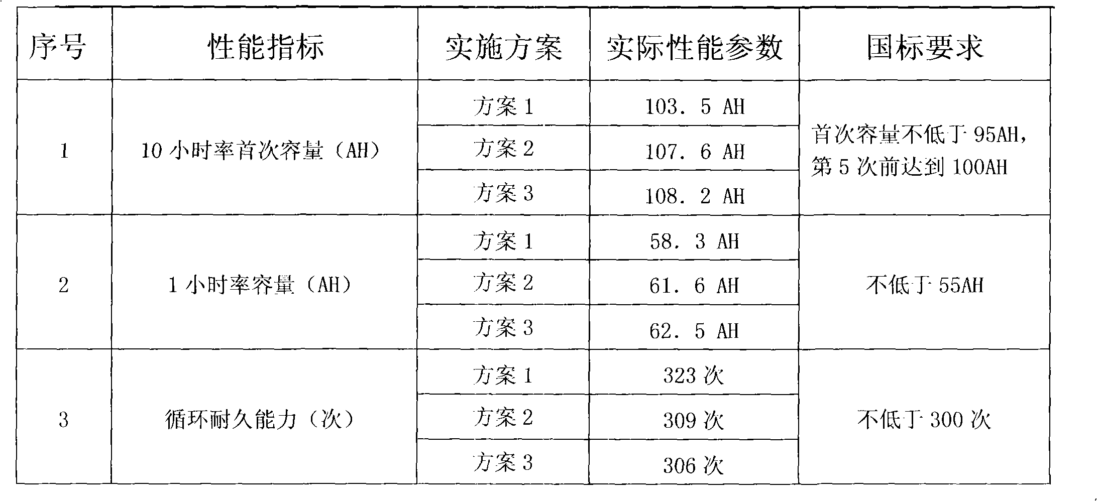
[0024] The performance indicators of the formed battery are as follows (take 12V100AH ​​as an example):

[0025]


PUM


Abstract

The invention discloses an internalized charging method for a standby lead-acid battery. The total internalized charging amount is 5 to 7 times the rated capacity of the battery, and the total charging time is 95 to 105 hours. The maximal charging current is 0.15C10, and the minimal charging current is 0.03C10 through discharging twice, charging for six times and standing once. The method comprises the following steps of: placing the battery poured with acid in a circulator water bath within 5 minutes, and simultaneously connecting the charging circuit of the battery for charging; and starting a charger for charging when the temperature of the battery reduces below 40 DEG C, wherein the temperature of the battery is required to be below 50 DEG C in the whole charging process. The initial capacity is not less than 100 percent of the rated capacity by adopting the internalized charging method, and the recycling service life is longer than that of a tank formation battery and international requirements.

Description

technical field [0001] The invention relates to a spare lead-acid battery, in particular to a method for internalizing and charging the spare lead-acid battery. Background technique [0002] At present, domestic manufacturers of backup batteries mainly use tanking for the initial charging of batteries. At the same time, many well-known domestic companies are also developing and researching battery internal formation. Compared with tank formation, battery internal formation has many advantages. Its technological process saves the process of plate washing, drying, and tank formation. It saves a lot of man-hours and energy, occupies a small area, and does not need to purchase formation tank equipment and acid mist prevention equipment, and the battery cost can be reduced to a certain extent. Moreover, the plate is not easily polluted by impurities, which can reduce the self-discharge of the battery, and the battery quality can be better controlled. Therefore, the internal form...

Claims


Application Information

Patent Timeline
IPC IPC(8): H01M10/44
CPCY02E60/10
Inventor 魏士洋朱志允
Owner ZHEJIANG TIANNENG BATTERY JIANGSU
Learn More