
Device and method for improving retransmission efficiency of communication system

A technology of communication system and efficiency, applied in transmission system, digital transmission system, using return channel for error prevention/detection, etc., which can solve problems such as low efficiency

Inactive Publication Date: 2010-10-06
WUHAN UNIV
View PDF3 Cites 11 Cited by
  • Summary
  • Abstract
  • Description
  • Claims
  • Application Information

AI Technical Summary

Problems solved by technology

This method of independently retransmitting multiple bit sequences at the transmitter is less efficient

Method used


Image

  • Device and method for improving retransmission efficiency of communication system
  • Device and method for improving retransmission efficiency of communication system
  • Device and method for improving retransmission efficiency of communication system

Examples


Embodiment 1

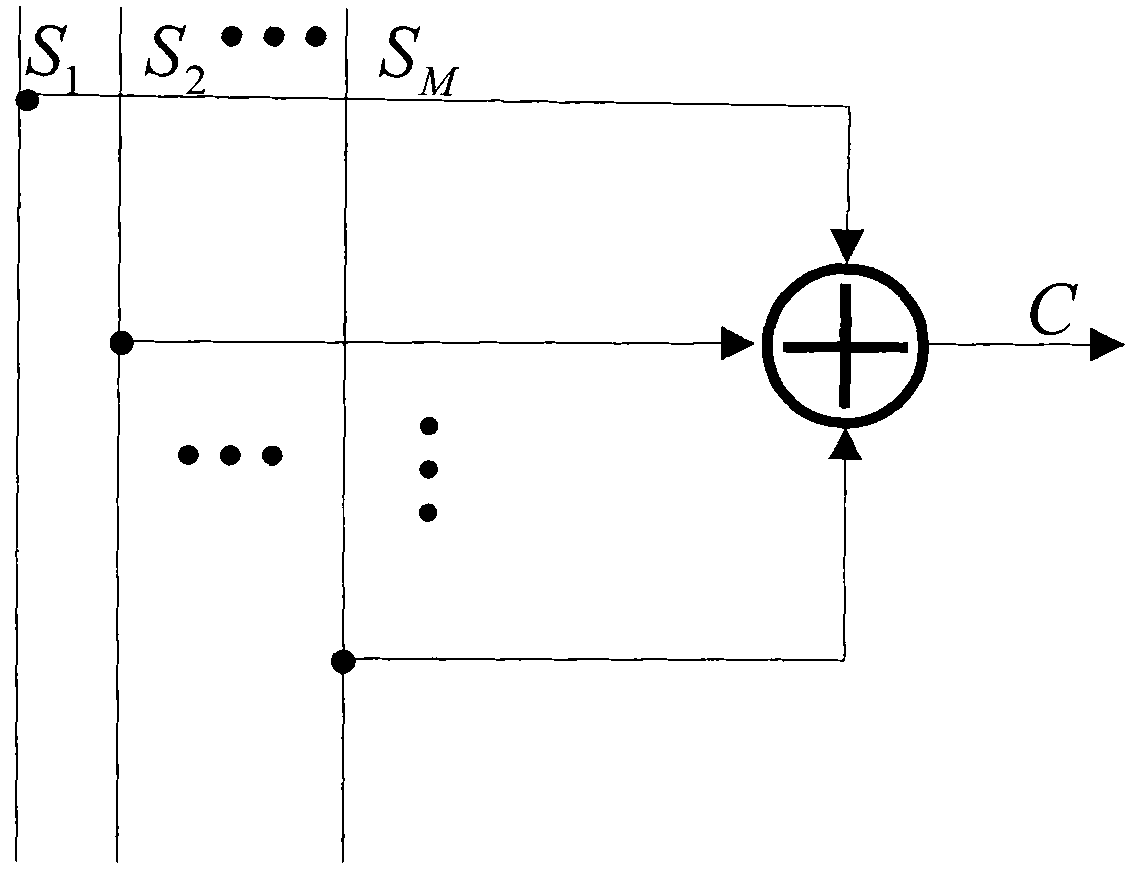
[0068] A device for improving the retransmission efficiency of a communication system, including an XOR encoder and a multi-packet detector, wherein the XOR encoder performs a bit-by-bit XOR operation on each input binary sequence, and outputs a combination after the XOR operation Data packet; when the lengths of the bit sequences input to the XOR encoder are inconsistent, each bit sequence is padded with '0' so as to be consistent with the length of the longest bit sequence.

[0069] The XOR encoder embedded in the transmitter uses the formula (1) to calculate the combined data packet retransmitted to the receiver:

[0070] c n = Σ j = 1 M s j , n - - - ( 1 )

[0071] In formula (1), M represents the number of...

Embodiment 2

[0081] A device for improving the retransmission efficiency of a communication system, including an XOR encoder and a multi-packet detector, the XOR encoder performs a bit-by-bit weighted XOR operation on each input binary sequence, and outputs the weighted XOR operation Combining data packets; when the lengths of the bit sequences input to the XOR encoder are inconsistent, each bit sequence is filled with '0' to be consistent with the length of the longest bit sequence.

[0082] The XOR encoder embedded in the transmitter uses formula (3) to calculate the combined data packet retransmitted to the receiver:

[0083] c n = Σ j = 1 M α j · s j , n - - - ( 3 )

[0084] In for...

Embodiment 3

[0095] A method for improving the retransmission efficiency of a communication system. The method performs XOR coding on each retransmitted binary sequence at a transmitting end, and then detects each retransmitted sequence from a combined data packet at a receiving end. The specific method is as follows:

[0096] On the transmitter side:

[0097] Step 1. Calculate the binary sequence S of each retransmission j (1≤j≤M) length;

[0098] Step 2. Calculate the binary sequence S of each retransmission j (1≤j≤M) the maximum value N in the length;

[0099] Step 3. Use '0' to convert the binary sequence S of length less than N j (1≤j≤M) is padded to length N, and the padding operation can be performed at the head or tail of the corresponding sequence;

[0100] Step 4. For each retransmitted binary sequence S j (1≤j≤M) perform bit-by-bit XOR operation, the method is as shown in formula (5);

[0101] c n = Σ ...


PUM


Abstract

The invention relates to the technical field of transmission of communication systems, in particular to a device and a method for improving retransmission efficiency of a communication system. An exclusive or coder is embedded into a transmitting end of a communication link and used for performing bit-by-bit exclusive or coding on a plurality of bit sequences retransmitted by the transmitting endand transmitting a combined data packet obtained after the exclusive or coding to a receiving end; and a multi-data packet detector is embedded into the receiving end of the communication link and used for detecting each retransmitted bit sequence from the combined data packet received by the receiving end. The exclusive or coder can merge and transmit the plurality of bit sequences retransmittedto the receiving end by the transmitting end, and the receiving end reduces each retransmitted bit sequence from the combined data packet by using the multi-data packet detector so as to save resources retransmitted from the transmitting end to the receiving end and further improve the retransmission efficiency of the communication system.

Description

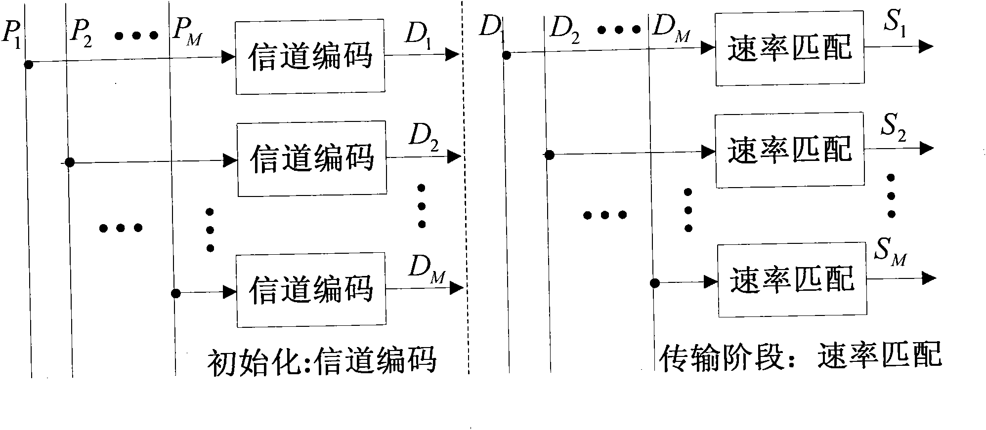
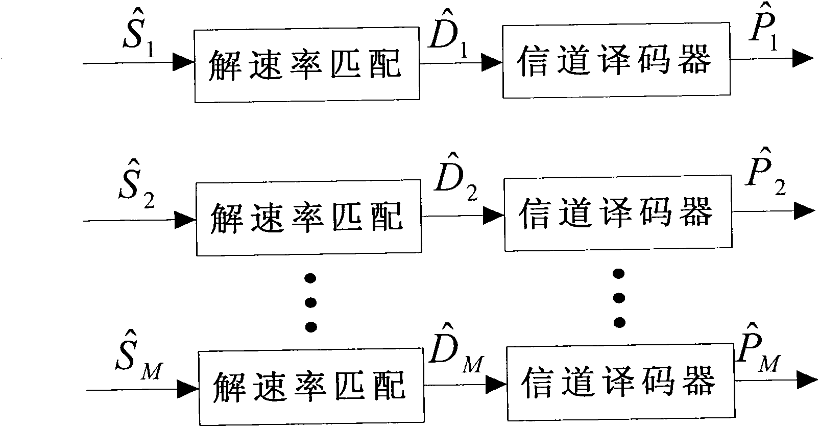
technical field [0001] The invention relates to the technical field of communication system transmission, in particular to a device and method for improving the retransmission efficiency of a communication system. Background technique [0002] Such as figure 1 As shown, in the current communication system, in the initialization phase, the M messages P transmitted by the transmitter to the receiver j (1≤j≤M) After channel coding, M binary codeword sequences D are obtained j (1≤j≤M), and D j (1≤j≤M) is buffered at the receiving end. In the transmission phase, M rate matchers are used to generate M encoded codeword sequences D j (1≤j≤M) Select M bit sequences S of specified length j (1≤j≤M), it is directly transmitted to the receiving end. Such as figure 2 The M soft bit sequences that the receiving end will receive After de-rate matching, M soft-coded codeword bit sequences are obtained Will After inputting to the channel decoder for decoding, M messages are obta...

Claims


Application Information

Patent Timeline
Patent Type & Authority Applications(China)
IPC IPC(8): H04L1/00H04L1/18
Inventor 王正海田茂
Owner WUHAN UNIV
Learn More