High-voltage power switch having a switch for engaging a starting resistor

A technology of power switch and closing resistor, which is applied in the direction of electric switch, switchgear setting, high voltage/high current switch, etc. It can solve the problems of high cost and achieve the effect of compact structure, small design and light structure.

Active Publication Date: 2010-10-06
HITACHI ENERGY SWITZERLAND AG
View PDF6 Cites 5 Cited by
  • Summary
  • Abstract
  • Description
  • Claims
  • Application Information

AI Technical Summary

Problems solved by technology

[0003] The known high-voltage power switch proves to be disadvantageous in that a costly mechanical arrangement comprising several parts is required for operating the circuit breaker unit and the switch
It also proves to be disadvantageous that in the case of an open high-voltage power switch, the spring of the switch determines the moment at which the switch opens

Method used


Image

  • High-voltage power switch having a switch for engaging a starting resistor
  • High-voltage power switch having a switch for engaging a starting resistor
  • High-voltage power switch having a switch for engaging a starting resistor

Examples


Embodiment Construction

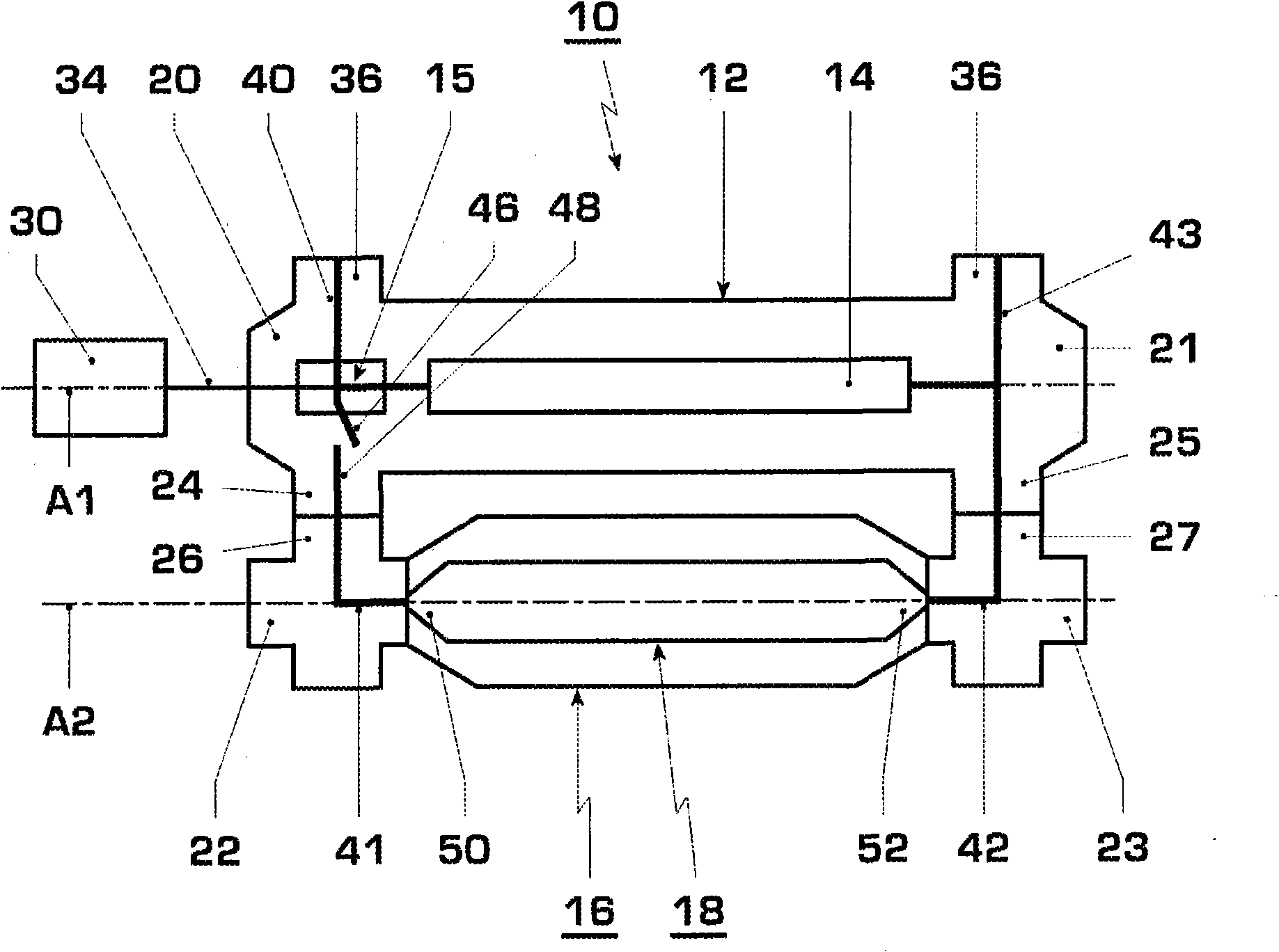
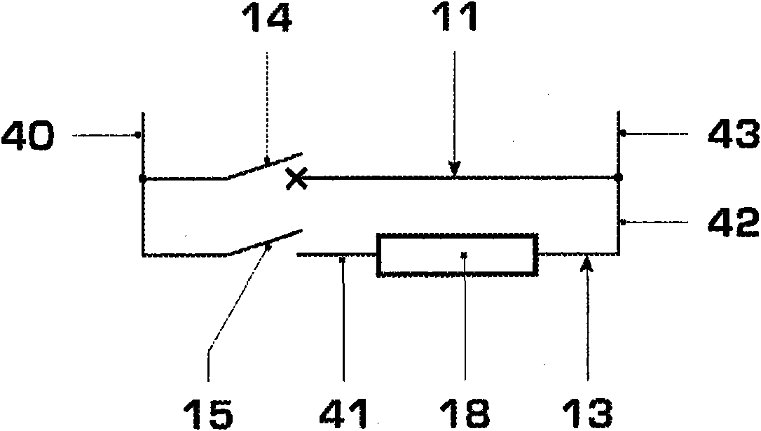
[0027] figure 1 A first embodiment of a metal-enclosed high-voltage power switch 10 for gas-insulated switchgear is shown. exist figure 2 The circuit diagram of the high voltage power switch is shown in . In this gas-insulated switchgear, sulfur hexafluoride (SF 6 ) is used as an insulating gas. Instead of the quenching gas ( ), other gases with good insulating properties can also be applied. Parallel to the main current path 11 , which can be interrupted by means of the circuit breaker unit 14 , a shunt current path 13 is conducted, which has a switch 15 and a closing resistor 18 connected in series with each other. Such a high-voltage power switch 10 is used for switching currents in grids above 400 kV (kilovolts), especially above 500 kV. A suitable switching resistor is disclosed in a patent application entitled "Einschaltwiderstand fuer Hochspannungsleistungschalter" filed on the same day by the same applicant, the entire disclosure content of which is incorporate...


PUM


Abstract

The invention relates to a high-voltage power switch having an interrupter unit (14), a starting resistor (18), and a switch (15) connected in series with the starting resistor (18). The interrupter unit (14) comprises a first interrupter contact (32) displaceable along an axis (A1) and driven, acting together with a second interrupter contact (33) disposed on the axis (A1) to open and close the high-voltage power switch. The switch (15) comprises a switch contact (46) pivotable about a pivot axis (D), the pivoting motion of which is coupled to the motion of the first interrupter contact (32) along the axis (A1) by means of a link motion (60).

Description

technical field [0001] The invention relates to a high-voltage power switch according to the preamble of claim 1 . Background technique [0002] One such high-voltage power switch is known from the publication US 4,499,350. The known high-voltage power switch has a main current path which can be disconnected by means of a circuit breaker unit. Parallel to the main current path, a shunt current path is conducted, in which the switch and the closing resistor are connected in series. The closing resistor is switched into the current circuit shortly before closing the contacts of the circuit breaker unit, so that the current flows through the shunt current path with the closing resistor shortly before closing the main current path. Therefore, a closing resistor is inserted into the current loop under load. The movable circuit breaker contact of the circuit breaker unit is driven by means of the lever and angle element of the drive unit. The driven contact of the switch is li...

Claims


Application Information

Patent Timeline
Patent Type & Authority Applications(China)
IPC IPC(8): H01H33/16
CPCH01H33/16H01H33/664H01H33/666H02B13/0352
Inventor W·霍劳斯D·索洛古伦-桑彻茨T·-J·威利U·克鲁西S·科蒂莱南M·霍尔斯坦A·阿亚K·乔汉M·加西亚M·凯勒
Owner HITACHI ENERGY SWITZERLAND AG
Why Eureka
Try Eureka