Plunger pump

A plunger pump and plunger technology, which is applied in the direction of pumps, multi-cylinder pumps, pump components, etc., can solve problems such as unevenness, impact of plunger pumps and hydraulic circuits, shortening service life of plunger pumps, etc., to prolong service life , reduce the impact, the effect of simple control form

Pending Publication Date: 2021-12-03
王丽娜
View PDF6 Cites 0 Cited by
  • Summary
  • Abstract
  • Description
  • Claims
  • Application Information

AI Technical Summary

Problems solved by technology

[0004] 1. In the prior art, due to the cooperation between the piston and the rotor of the plunger pump, the plunger cavity will be compressed when the plunger pump starts to work, so that the plunger pump will start with load and start at high pressure. The plunger pump and hydraulic circuit cause a lot of impact;
[0005] 2. When the plunger pump is started, since there is no uniform oil layer between the plunger and the rotor, there will be greater friction between the plunger and the rotor, which will shorten the service life of the plunger pump

Method used


Image

  • Plunger pump
  • Plunger pump
  • Plunger pump

Examples


Embodiment Construction

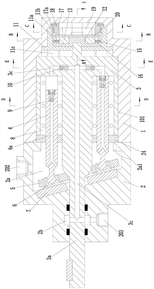
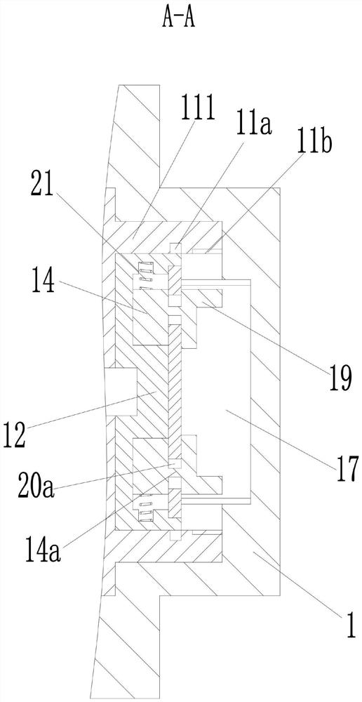
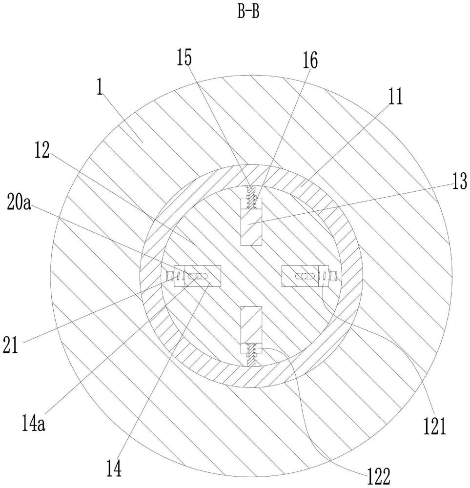
[0033] see Figure 1-14As shown, a plunger pump includes a pump body 1, the pump body 1 is provided with a pump chamber 101 with an open left end, the pump chamber 101 is rotatably connected to a rotor 3, and the rotor 3 is provided with an open left end The left end of the pump body 1 is fixed with a pump cover 2, and the pump cover 2 is provided with a slot 2a communicating with the pump chamber 101; the opening of the left end of the installation groove 301 is fixed with a guide Disk 24, the inner side wall of the slot hole 2a is radially provided with a protrusion 2a1 on the left side of the guide disk 24 near the opening of the right end; The disc 24 extends into the intermediate shaft 302 in the slot 2a, and the left end of the intermediate shaft 302 extends to the left and is provided with a power shaft 3a protruding from the pump cover 2; 3a outside the swash plate 7, the left end of the intermediate shaft 302 is sleeved with the return plate 5 parallel to the swash p...


PUM


Abstract

The invention discloses a plunger pump. The plunger pump comprises a pump body; a pump cavity is formed in the pump body; a rotor is rotationally connected into the pump cavity; a mounting groove is formed in the rotor; a pump cover is fixedly arranged at the left end of the pump body; a groove hole is formed in the pump cover; a guide disc is fixedly arranged at an opening in the left end of the mounting groove; an intermediate shaft is arranged in the mounting groove; a power shaft is arranged at the left end of the intermediate shaft; a swash plate is fixedly arranged in the groove hole; the left end of the intermediate shaft is sleeved with a return plate; sliding shoes are arranged in the return plate; cylinder block assemblies are arranged in the mounting groove; the guide disc is provided with plungers; the left end of each plunger is in ball hinge joint with the inside of the corresponding sliding shoe; an oil inlet and an oil outlet are formed in the outer side of the pump cover; and a valve control assembly is arranged in the pump body. The plunger pump not only is simple in structure, but also can realize no-load starting and reduce impact on a loop.

Description

technical field [0001] The invention relates to the technical field of hydraulic components, in particular to a plunger pump. Background technique [0002] The plunger pump is an important device of the hydraulic system. It relies on the reciprocating movement of the plunger in the cylinder to change the volume of the sealed working chamber to realize functions such as oil absorption and oil pressure. Because the plunger pump has the advantages of high rated pressure, compact structure, high efficiency and convenient flow adjustment, it is widely used in high pressure, large flow and flow adjustment occasions, such as petroleum machinery, hydraulic presses, engineering machinery and ships. [0003] The following problems generally occur when the existing plunger pump is used: [0004] 1. In the prior art, due to the cooperation between the piston and the rotor of the plunger pump, the plunger cavity will be compressed when the plunger pump starts to work, so that the plunge...

Claims


Application Information

Patent Timeline
IPC IPC(8): F04B1/0408F04B1/0421F04B53/18F04B53/00
CPCF04B1/0408F04B1/0421F04B53/18F04B53/008
Inventor 王丽娜程建军刘欣
Owner 王丽娜
Why Eureka
Try Eureka