Integrated shearing and bent reshaping clamp device of optical device pin

An optical device and pin technology, applied in the field of optical communication production and processing, can solve the problems of device pin root damage, high personnel skill requirements, poor consistency, etc., to reduce the risk of damage, low employee skill requirements, and reduce production. The effect of the process

Active Publication Date: 2010-10-13
成都新易盛通信技术股份有限公司
View PDF6 Cites 15 Cited by
  • Summary
  • Abstract
  • Description
  • Claims
  • Application Information

AI Technical Summary

Problems solved by technology

[0002] The current cutting of device pins and bending and shaping of device pins are all done by hand, so the consistency of cutting an

Method used


Image

  • Integrated shearing and bent reshaping clamp device of optical device pin
  • Integrated shearing and bent reshaping clamp device of optical device pin
  • Integrated shearing and bent reshaping clamp device of optical device pin

Examples


Embodiment Construction

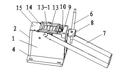
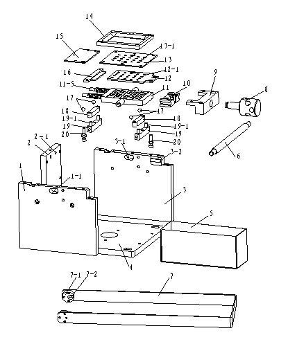
[0024] like Figure 1-9 As shown, an optical device pin cutting and bending shaping jig integrated device, including a hollow square surrounded by the left side plate 1, the right side plate 3, the vertical plate 2 and the base 4, which is the supporting overall structure The important components, and the rest of the components are based on this hollow square. The collection box 5 is placed in the hollow box and below the knife plate 11, and is mainly used to collect the redundant pins that have been cut. The oblong hole 1-1 provided above the left side plate 1 corresponds to the oblong hole 3-1 provided above the right side plate 3, and the left side plate 1 and the right side plate 3 are located in the oblong hole 1-1 , Both sides of the oblong hole 3-1 are respectively connected with a support member 19 by screws, and the support member 19 is provided with two cylinders 19-1 matching the cylindrical holes on the top block 18, and the top block 18 passes through the two Th...


PUM


Abstract

The invention discloses an integrated shearing and bent reshaping clamp device of an optical device pin, belonging to the technical field of shearing and bent reshaping clamps of the optical device pins and comprising a hollow box formed by surrounding a left side plate, a right side plate, a vertical plate and a base. A support member is connected to the left side plate and the right side plate and is connected with a top block on which balls are arranged, and a cutting plate is placed on the balls and is connected with an eccentric wheel at the end part of an rocking handle; and the left side plate and the right side plate are clamped with a slide block which is connected with a screw rod through a screw rod fixing block, the slide block is sheathed with a lower plate above which an upper plate is arranged, strip-shaped holes for the optical device pin to be reshaped to penetrate through are correspondingly arranged on the upper plate, the lower plate and the cutting plate, and a blade for shearing the optical device pin to be reshaped is arranged in the strip-shaped hole of the cutting plate. The invention has the advantages of simple operation and good consistency of a shearing effect and a bent reshaping effect, reduces production procedures, improves production efficiency and effectively lowers the risk of damaging the root of the device pin.

Description

technical field [0001] The invention relates to the field of optical communication production and processing, in particular to a jig for cutting, bending and shaping optical device pins. Background technique [0002] The current cutting of device pins and bending and shaping of device pins are all done by hand, so the consistency of cutting and bending and shaping is poor; the requirements for personnel skills are high; the efficiency is not high and laborious; risk of injury. Contents of the invention [0003] The object of the present invention is to provide an integrated device for cutting and bending and shaping jigs for optical device leads that effectively combines the two functions of cutting and bending and shaping optical device leads. [0004] The technical solution of the present invention is: an integrated device for cutting and bending and shaping the pins of an optical device, comprising a hollow square surrounded by a left side plate, a right side plate, a ...

Claims


Application Information

Patent Timeline
IPC IPC(8): B21F11/00B21F1/00
Inventor 黄晓雷丁亚军周美娜
Owner 成都新易盛通信技术股份有限公司
Why Eureka
Try Eureka