Radio identification label making device

A technology for wireless identification and production of devices, applied to record carriers, instruments, computer parts and other directions used in machines, and can solve problems such as unstable transmission, damage to IC chips, antenna parts, sheet parts, and printing penetration.

Active Publication Date: 2010-10-13
BROTHER KOGYO KK
View PDF2 Cites 6 Cited by
  • Summary
  • Abstract
  • Description
  • Claims
  • Application Information

AI Technical Summary

Problems solved by technology

[0010] However, in the above-mentioned wireless identification tag, there are still problems related to the identification printing attached thereto, the IC chip embedded therein, and the antenna conductor when it is actually used.
[0011] For example, when attaching an image to the above-mentioned wireless identification tag, when the image is formed after making a wireless identification tag containing an IC chip or the like, it may be affected by the unevenness of the image forming surface formed due to the thickness of the IC chip or the like. The formed image is distorted, or when an object touches the image forming surface, the image is wiped and becomes unclear. In the case of a heat-sensitive method that heats the image forming surface to form an image, etc., due to the image forming process applied to the wireless identification tag The heat will cause damage to the resonant circuit contained in the wireless identification tag, or the junction of the IC chip or the antenna conductor, etc.
[0012] In addition, when a sheet member for a wireless identification tag containing an IC chip, an antenna conductor, etc. is accommodated, the thickness of the IC chip and the antenna conductor expands, so it is difficult to hold the adjacent wireless identification tag in the thickness direction when winding. In the closely bonded state of the sheet parts, gaps are generated, easy to loosen, and gaps formed by IC chips and antenna conductors are formed. If the sheet parts for wireless identification tags are directly wound, it may occur: Can be accommodated in the storage area The number of tags decreases, the frequency of replenishment of sheet parts for wireless identification tags becomes higher, and the storage area increases when a large number of tags are to be accommodated, resulting in an increase in the overall size of the wireless identification tag manufacturing device, or due to entangled wireless identification tags. At least one of the IC chip, the antenna part, or the sheet parts may be damaged due to wear and static electricity generated by friction when the sheet parts are misaligned
[0013] In addition, the structure of the wireless identification tag is that the IC chip and the antenna conductor connected thereto are arranged on one side of the strip-shaped sheet member, but since the places where the IC chip and the like are arranged become locally thick, there are problems as follows: The strip-shaped wireless identification tags stored in the state of being wound up before being cut, and the short pieces of wireless identification tags stored in the cut state require more storage space when stored in a box, etc.
[0014] And, in making the above-mentioned existing wireless identification tag manufacturing device by embedding the IC chip with wireless identification function and the wireless identification antenna conductor, since the larger IC chip and the thicker IC chip are embedded in the strip-shaped sheet member The wireless identification antenna conductor, therefore, the IC chip and the wireless identification antenna conductor protrude from the strip-shaped sheet member. When the strip-shaped sheet member is wound into a roll shape, the protruding amount overlaps. When the wireless identification label is produced in the wireless identification label production device, the IC tag and the wireless identification antenna conductor are pushed by the conveying roller during the label production process, so that the load on the IC chip and the wireless identification antenna conductor increases, and there may be: IC The circuit inside the chip is short-circuited, the identification data stored inside disappears due to the deterioration of the IC chip, and the IC chip, the wireless identification antenna conductor, and the joint between the IC chip and the wireless identification antenna conductor are damaged
In addition, when the belt-shaped sheet member protruding from the information identification part including the antenna conductor and the IC chip is transported by rollers, it may occur that the transmission becomes unstable due to the influence of the protrusion and the inclination occurs, and the part protruding from the information identification part may appear. In the process of printing strip-shaped sheet parts, the conveying speed changes between the front and back of the protruding part, and problems such as bleeding and misalignment of printing occur.

Method used


Image

  • Radio identification label making device
  • Radio identification label making device
  • Radio identification label making device

Examples


no. 1 approach

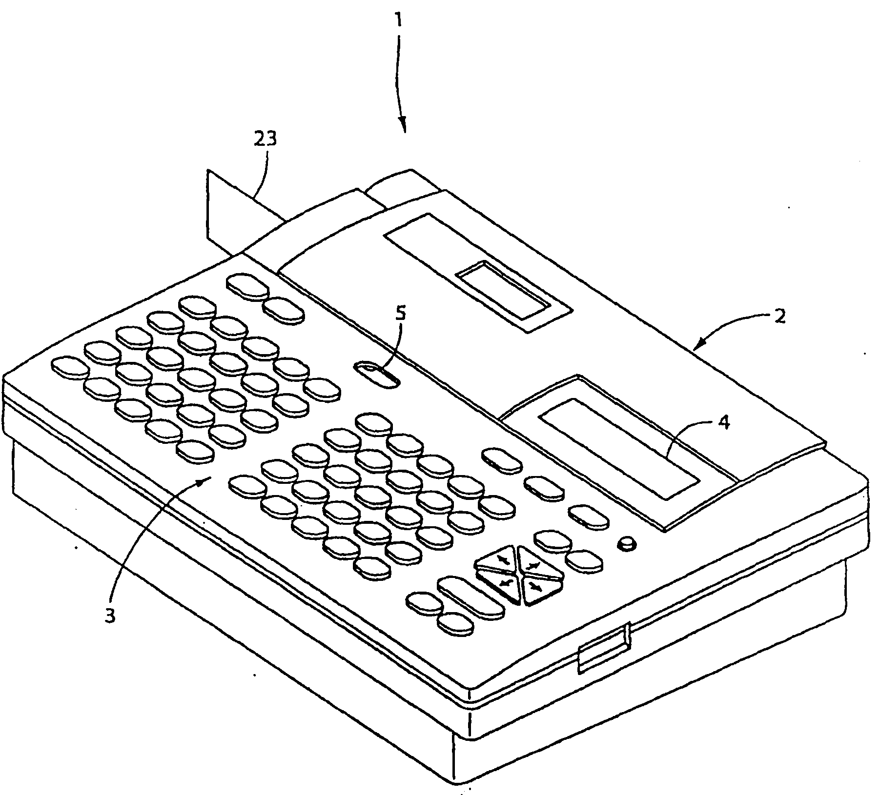
[0073] figure 1 It is a perspective view showing the whole of the wireless identification tag manufacturing apparatus 1 for manufacturing a wireless identification tag 70 called a wireless tag or the like.

[0074] exist figure 1 Among them, a keyboard 3 is arranged at the front of the wireless identification label making device 1, and a thermal printing mechanism PM corresponding to the image forming unit of the present invention is arranged inside the wireless identification label making device 1 behind the keyboard 3 (refer to figure 2 ). And, on the rear side of the keyboard 3 there is a figure 2 The illustrated box 10 is provided as an openable and closable cover case 2 , and a display 4 such as a liquid crystal display (LCD) for displaying input characters, symbols, and the like is arranged in the cover case 2 . Furthermore, an operation knob 5 for opening and operating the cover 2 is arranged between the cover 2 and the keyboard 3 .

[0075] Keyboard 3 is provided...

no. 2 approach

[0119] Next, other embodiments of the present invention will be described. In addition, in the following description, the same reference numerals are assigned to the same parts as those of the above-mentioned embodiment, and the description thereof will be omitted.

[0120] Figure 7 (A) is a side sectional view of the wireless identification tag 70 using the laminated tape 11 of another form. Should Figure 7 The wireless identification tag 70 shown is the same as that described above (refer to Figure 4 and Figure 5 ) The wireless identification tag 70 differs only in the laminated tape 11 used to make the wireless identification tag 70 .

[0121] Figure 7 The laminated tape 11 of the embodiment of (A) is not a simple transparent film, but contains a coupler prepared in such a way that the heated portion is colored by local heating on the side of the tape-shaped sheet member 16 to be bonded. , and has a heat-sensitive layer 11A, so that the partial coloration is a pr...

no. 3 approach

[0154] Figure 11 It shows a case in which a square or rectangular sheet member 16 or a wireless identification tag 70 is housed in a box P as a package shown by a dotted line for single product sales of the strip-shaped sheet member 16 . At this time, each tape is peeled off one by one and conveyed, and the wireless identification tag 70 is manufactured sequentially. Even in this case, the image printed on the wireless identification tag 70 can be kept in good condition without damaging the IC chip 64 and the like inside the wireless identification tag 70 .

[0155] In addition, in the thickness direction, between the adjacent sheet members 16 or RFID tags 70, the IC chips 64 are staggered and arranged in the plane direction, so that the box P can be reduced in size, or it can be accommodated in boxes P of the same size. There are many sheet members 16 or wireless identification tags 70 .


PUM


Abstract

Provided is a radio identification label making device. When creating a radio identification label (70) by attaching a transparent first label substrate to a belt-shaped sheet member (16) including a radio identification antenna conductor or an IC chip (64), an image is formed on a laminate tape (11) not containing the IC chip (64) or the like before attaching the laminate tape (11) to the belt-shaped sheet member (16). Moreover, when forming an image on the laminate tape (11), the image is formed on the side of the laminate tape (11) which side is attached to the belt-shaped sheet member (16). Thus, it is possible to preferably maintain the state of the image printed on the radio identification label (70) without damaging the IC chip (64) or the like arranged inside.

Description

[0001] This application was submitted on March 24, 2004, the application number is 200480011845.5 (international application number is PCT / JP2004 / 004120), and the invention title is "wireless identification tag, its manufacturing method, manufacturing device, sheet for wireless identification tag Components, and boxes installed on its production equipment for the production of wireless identification tags" is a divisional application of the application. technical field [0002] The present invention relates to a wireless identification tag capable of wirelessly recording or reading information data, a method for manufacturing the wireless identification tag, a manufacturing device for the wireless identification tag, a sheet member for the wireless identification tag, and a wireless identification tag that can be mounted on a wireless identification tag. The box on the crafting device. Background technique [0003] In the prior art, as an example of wirelessly processing dat...

Claims


Application Information

Patent Timeline
Patent Type & Authority Applications(China)
IPC IPC(8): G06K19/07G06K19/077
CPCG06K19/07718G06K19/07796G06K19/07749G06K19/0776
Inventor 大桥勉泷和也安井邦博永井拓也高桥寿生中村康宪
Owner BROTHER KOGYO KK
Why Eureka
Try Eureka