
Power-line carrier electrodeless lamp control receiver

A technology of power line carrier and electrodeless lamps, which is applied in distribution line transmission systems, the use of gas discharge lamps, electric light sources, etc., can solve the problems of high-pressure sodium lamp decay, inability to control individually or centrally, and high operating frequency, and achieve upgrades Easy to replace and solve the problem of long-distance communication

Inactive Publication Date: 2013-08-28
WEIHAI DONGXING ELECTRONICS
View PDF5 Cites 0 Cited by
  • Summary
  • Abstract
  • Description
  • Claims
  • Application Information

AI Technical Summary

Problems solved by technology

In public lighting, street lighting accounts for a considerable proportion. At present, high-pressure sodium lamp lighting is commonly used. Due to the large decay of high-pressure sodium lamps, in order to maintain the brightness for a certain period of time, most places artificially increase the lighting power of high-pressure sodium lamps. This will greatly waste a large amount of electric energy. In order to solve this problem, many new light sources that can replace high-pressure sodium lamp lighting have appeared.
Electrodeless lamps are the most cost-effective street lighting products among new light sources. Most areas have begun to install them in large quantities. However, since the working frequency of both high-frequency and low-frequency electrodeless lamps is relatively high, the existing centralized controllers cannot For its individual or centralized control, it is necessary to develop a controller according to the working characteristics of the electrodeless lamp to replace the current old controller

Method used


Image

  • Power-line carrier electrodeless lamp control receiver
  • Power-line carrier electrodeless lamp control receiver

Examples


Embodiment Construction

[0016] The present invention will be further described below in conjunction with the accompanying drawings and specific embodiments, so as to help understand the content of the present invention.

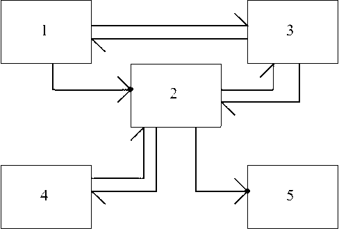
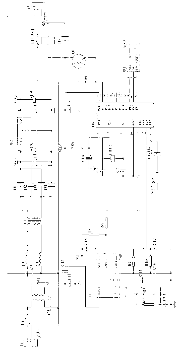
[0017] like figure 1 As shown, the present invention is made up of power supply circuit 1, microcontroller MCU control circuit 2, digital demodulation circuit 3, clock and data control circuit 4 and output control circuit 5, microcontroller MCU control circuit 2 and power supply circuit 1, digitization The demodulation circuit 3, the clock and data control circuit 4, and the output control circuit 5 are connected, the power supply circuit 1 provides power for the microcontroller MCU control circuit 2, the digital demodulation circuit 3, and the output control circuit 5, and the clock and data control circuit 4 is Microcontroller MCU control circuit 2 provides accurate time and data storage withdrawal. The output control circuit 5 is used to control the lighting conditions of the e...


PUM


Abstract

The invention relates to a power-line carrier electrodeless lamp control receiver which belongs to the field of lighting product application. The power-line carrier electrodeless lamp control receiver consists of a power supply circuit, a micro control unit (MCU) control circuit, a digital demodulation circuit, a clock, a data control circuit and an output control circuit, wherein the micro control unit (MCU) control circuit is connected with the power supply circuit, the digital demodulation circuit, the clock, the data control circuit and the output control circuit; the power supply circuit provides a power supply for the micro control unit (MCU) control circuit, the digital demodulation circuit and the output control circuit; the clock and the data control circuit provide precise time and data storage and retrieval for the micro control unit (MCU) control circuit; the output control circuit is used for controlling the lighting condition of the electrodeless street lamp; and the micro control unit (MCU) control circuit is a control core and is used for controlling the coordination among other circuits. The invention can remotely control the lighting condition of the electrodeless street lamp or automatically control the lighting condition of the electrodeless street lamp according to the time and preset parameters. The invention has the advantages of high cost performance and low initial investment.

Description

technical field [0001] The invention relates to the application field of lighting products, in particular to a lighting controller for an electrodeless street lamp. Background technique [0002] As we all know: At present, electricity consumption in the lighting field accounts for 25% of all electricity consumption, while public lighting accounts for 30% of lighting electricity consumption. In public lighting, street lighting accounts for a considerable proportion. At present, high-pressure sodium lamp lighting is commonly used. Due to the large decay of high-pressure sodium lamps, in order to maintain the brightness for a certain period of time, most places artificially increase the lighting power of high-pressure sodium lamps. Doing so will greatly waste a large amount of electric energy. In order to solve this problem, many new light sources that can replace high-pressure sodium lamp lighting have appeared. Electrodeless lamps are the most cost-effective street lighting...

Claims


Application Information

Patent Timeline
Patent Type & Authority Patents(China)
IPC IPC(8): H05B41/36H04B3/54
CPCY02B20/202Y02B20/00
Inventor 张现金
Owner WEIHAI DONGXING ELECTRONICS
Learn More