Rotary folding type hydraulic channeling machine

A technology of folding and grooving machines, which is applied in the field of hydraulic grooving machines, which can solve problems such as low work efficiency, large differences in pipe sizes, and incorrect positioning of workpieces, and achieve labor-saving, convenient, and efficient effects.

Active Publication Date: 2010-10-20
浙江唯特利图伟管道设备有限公司
View PDF0 Cites 9 Cited by
  • Summary
  • Abstract
  • Description
  • Claims
  • Application Information

AI Technical Summary

Problems solved by technology

But existing grooving machine has following shortcoming: the one, main body (comprising power and grooving mechanism) is fixed with frame, because some pipes are relatively long (as 5, 6 meters long), need to be assisted at the other end of pipes Bracket support, because the position of the bracket is not easy to align, the pipe and the machine are in an inclined state, and because the long pipe itself has problems such as deformation or bending, the length and weight of the pipe when the machine is working makes the machine unable to control the correct position, and the workpiece cannot b

Method used


Image

  • Rotary folding type hydraulic channeling machine
  • Rotary folding type hydraulic channeling machine
  • Rotary folding type hydraulic channeling machine

Examples


Embodiment Construction

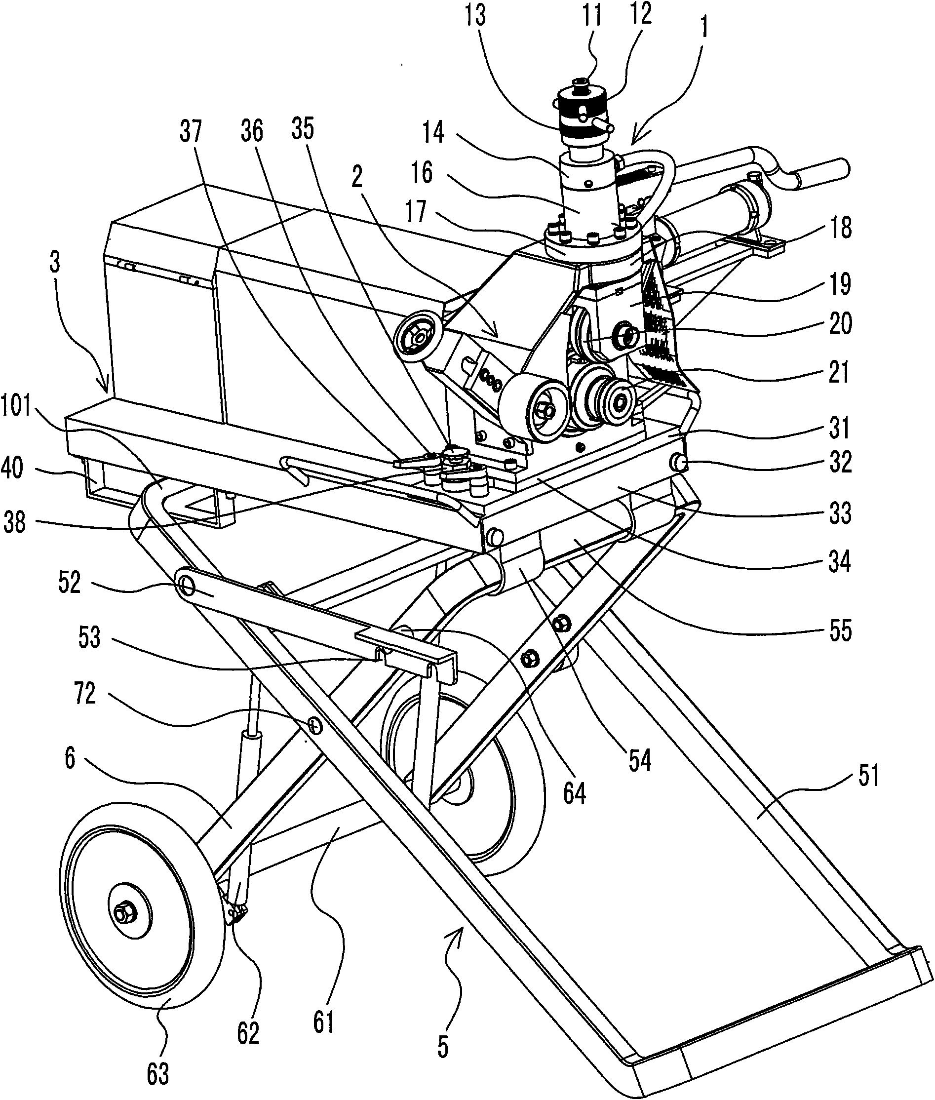
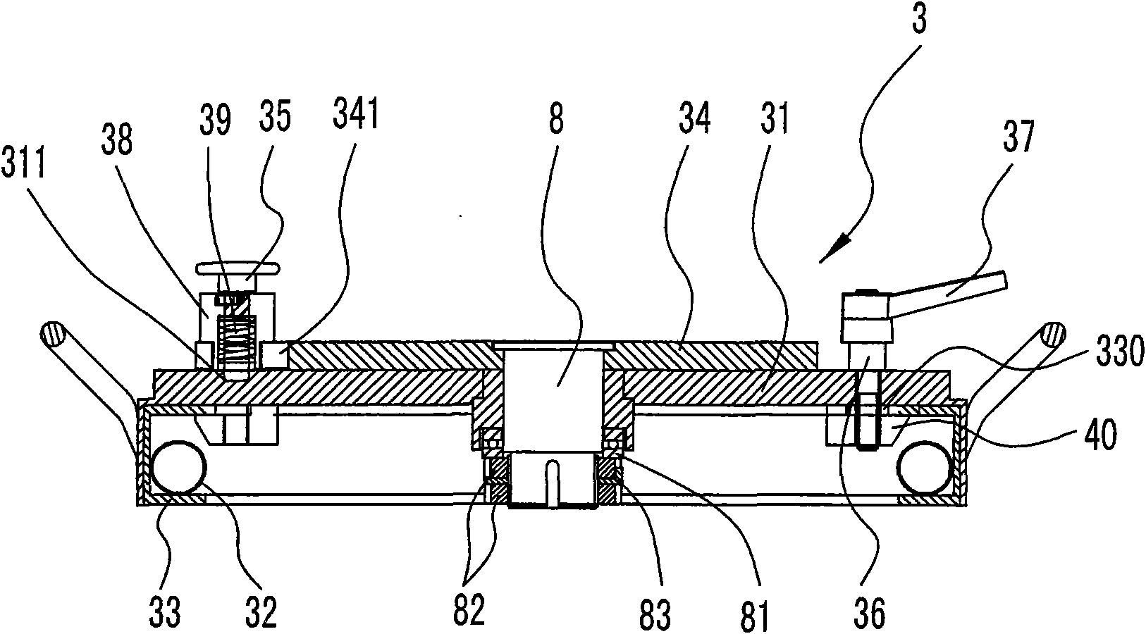
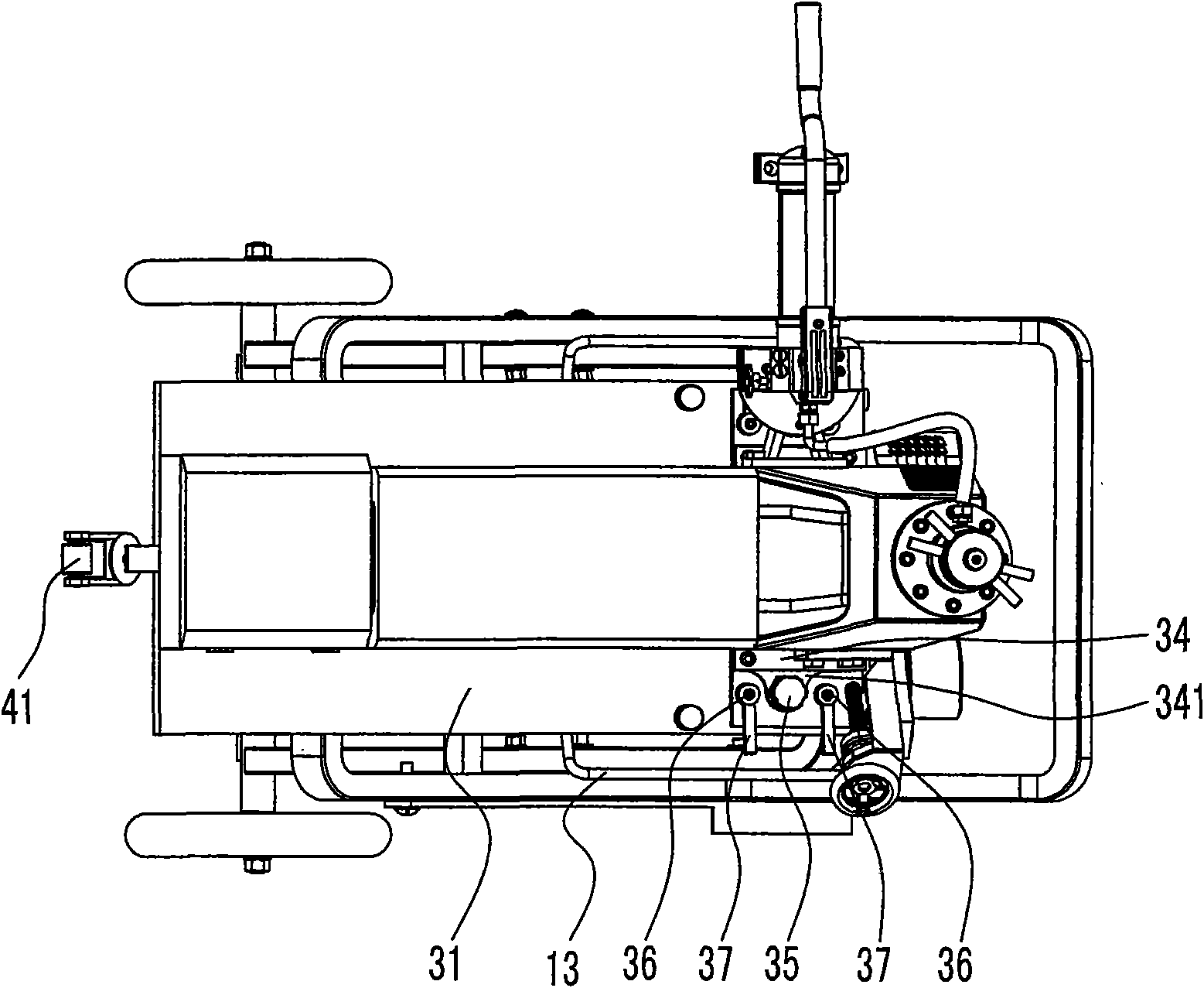
[0013] The invention relates to a rotating and folding hydraulic grooving machine, such as Figure 1-Figure 6As shown, it includes a main body and a frame. The main body includes a power head 2 and a rolling mechanism 1. The power head includes a main shaft driven by power, and the main shaft drives a knurled shaft 21. The rolling mechanism 1 described above comprises an oil cylinder body 16, the oil cylinder body is connected with an oil cylinder cover 14 and a bottom plate 17 of the oil cylinder, a piston 15 and a piston rod 11 are installed in the oil cylinder body, the lower end of the piston rod is connected with a movable block 18, and the movable block is connected with a pressure wheel Frame 19, the pressure roller 20 is installed in the pressure wheel frame, the main body is installed on the flat panel assembly 3, and the flat panel assembly 3 is connected to the frame 5. It is characterized in that there is a rotating device in the flat panel assembly 3, and the main ...


PUM


Abstract

The invention relates to a rotary folding type hydraulic channeling machine, which comprises a body and a machine frame, wherein the body comprises a motive power head and a rolling mechanism, wherein the rolling mechanism comprises an oil cylinder body, an oil cylinder cover and an oil cylinder bottom plate, a piston and a piston rod are arranged in the oil cylinder body, the body is arranged on a flat plate assembly, a rotating device is arranged in the flat plate assembly, the flat plate assembly comprises a flat plate, the upper part of the flat plate is connected with a transition plate through a rotating shaft, the body is arranged on the transition plate, the transition plate rotates around the rotating shaft in a swinging way, the rotary folding type hydraulic channeling machine is also provided with a swinging position limiting device, the flat plate and the transition plate are provided with a braking mechanism, the flat plate is arranged on a flat plate frame, the machine frame is connected under the flat plate frame, the flat plate slides on the flat plate frame, the flat plate and the flat plate frame are provided with a locking mechanism, the machine frame is an air spring auxiliary support folding machine frame which comprises two opening hinges arranged under the front end of the flat plate frame, the opening hinges are connected with a short support rod, a position limiting strip is arranged under the tail end of the flat plate frame, a long support rod is surrounded by the position limiting strip and the flat plate frame, the long support rod and the short support rod are connected through a connecting shaft, a position limiting plate is arranged on the long support rod, a position limiting groove is arranged in the position limiting plate, a position limiting pin is fixed on the short support rod, and the position limiting pin is matched with the position limiting groove.

Description

technical field [0001] The invention relates to a hydraulic grooving machine, in particular to a grooving machine in which the main body and frame of the machine can be rotated, and the frame can be folded up and down. The ring groove is rolled on the inside to install the ring pipe clip, so as to achieve the purpose of quickly installing the pipe. It belongs to the equipment for pipe installation in building construction. Background technique [0002] In housing construction, water supply and drainage pipelines need to be installed, and the two pipes in the pipeline need to be connected to each other. The traditional technology usually uses flange connection. The flange connection needs to be welded and fixed with fasteners. The construction is cumbersome, sparks will be generated, and fasteners such as screws are easy to loosen. Therefore, in recent years, a rolling grooving machine has been developed, which rolls out an annular groove on the end of the pipe, and installs...

Claims


Application Information

Patent Timeline
IPC IPC(8): B21D17/04
Inventor 杨岩顺
Owner 浙江唯特利图伟管道设备有限公司
Why Eureka
Try Eureka