Heat deformation detection instrument

A detector and thermal deformation technology, applied in the direction of mechanical solid deformation measurement, etc., can solve the problems of relatively large fluctuation of measurement data, affecting the accuracy of measurement data, affecting the accuracy of test data, etc., to ensure accuracy, low cost, accurate high degree of effect

Inactive Publication Date: 2010-10-20
宁波市产品质量监督检验研究院
View PDF4 Cites 11 Cited by
  • Summary
  • Abstract
  • Description
  • Claims
  • Application Information

AI Technical Summary

Problems solved by technology

[0003] The existing thermal deformation detector includes an oven, a dial gauge outside the oven, and a sample holder inside the oven. When measuring, the sample is placed in the sample holder and the dial gauge is used to measure the deformation of the sample. , has the advantages of simple structure and convenient use. However, since the dial indicator is located on one side of the sample holder, the sample may be inclined in all directions after deformation, which will seriously affect the accuracy of the test data; at the same time, because the dial indicator The weight of itself may affect the deformation of the sample under a certain load, resulting in relatively large fluctuations in measurement data; since the vent hole of the oven is generally located in the center of the upper part of the oven, the dial indicator needs to pass through the vent hole of the oven and the oven. The internal sample holder is connected, because the dial gauge is located on one side of the sample holder, so the sample in the sample holder is located at the edge of the oven, resulting in uneven heating of the sample in the oven, which will also affect the accuracy of the measurement data sex

Method used


Image

  • Heat deformation detection instrument
  • Heat deformation detection instrument
  • Heat deformation detection instrument

Examples


Embodiment 1

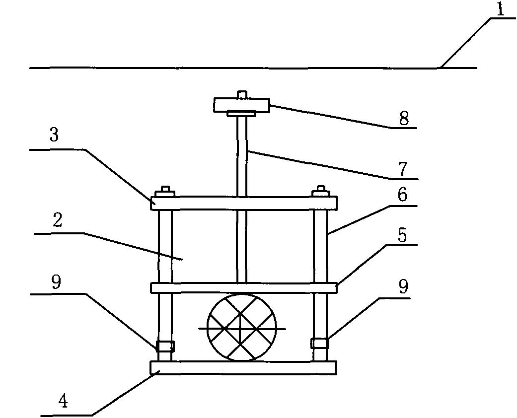
[0016] Such as figure 1 As shown, a thermal deformation detector includes an oven (1), and a sample rack (2) is arranged inside the oven (1). The sample rack includes an upper plate (3), a lower plate (4) and a horizontally arranged upper plate. The load pressing plate (5) between the plate (3) and the lower plate (4), the four corners of the sample holder (2) are provided with guide posts 6 for fixing the upper plate (3) and the lower plate (4), and the guide posts (6 ) vertically through the load platen (5), the load platen (5) can move up and down along the guide post (6), the load platen (5) is vertically provided with a load bar (7) in the center of the upper surface, the load bar (7) passes through The upper plate (3) is connected to the load-bearing plate (8) provided outside the sample holder, and the displacement measuring device (9) is set on the guide post (6) between the load platen (5) and the lower plate (4), namely the cursor .

[0017] experiment procedure: ...

Embodiment 2

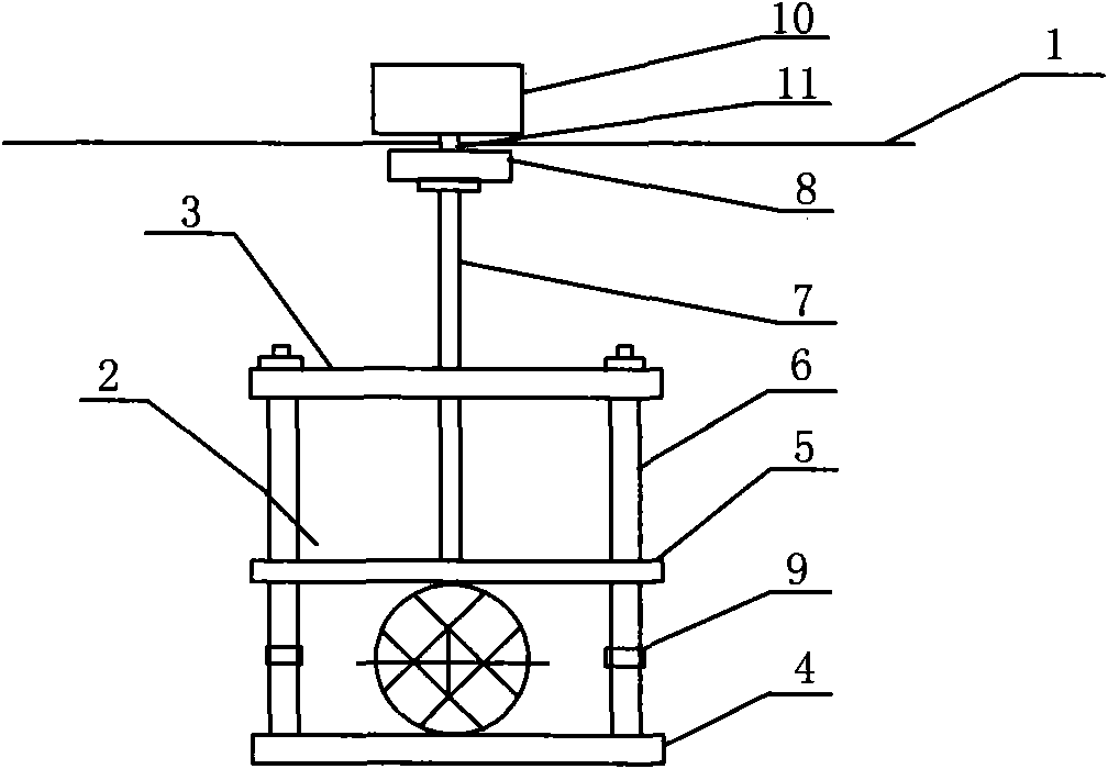
[0031] Such as figure 2 As shown, a thermal deformation detector includes an oven (1), and a sample rack (2) is arranged inside the oven (1). The sample rack includes an upper plate (3), a lower plate (4) and a horizontally arranged upper plate. The load pressing plate (5) between the plate (3) and the lower plate (4), the four corners of the sample holder (2) are provided with guide posts (6) for fixedly connecting the upper plate (3) and the lower plate (4), the guide The column (6) passes through the load pressing plate (5) vertically, and the load pressing plate (5) can move up and down along the guide column (6). 7) Pass through the upper plate (3) and connect with the load-bearing plate (8) provided outside the sample holder, and a displacement measuring device (9) is provided on the guide column (6) between the load platen (5) and the lower plate (4). ) is the displacement sensor, and the oven (1) is provided with a displacement sensor display interface (10) used in c...

Embodiment 3

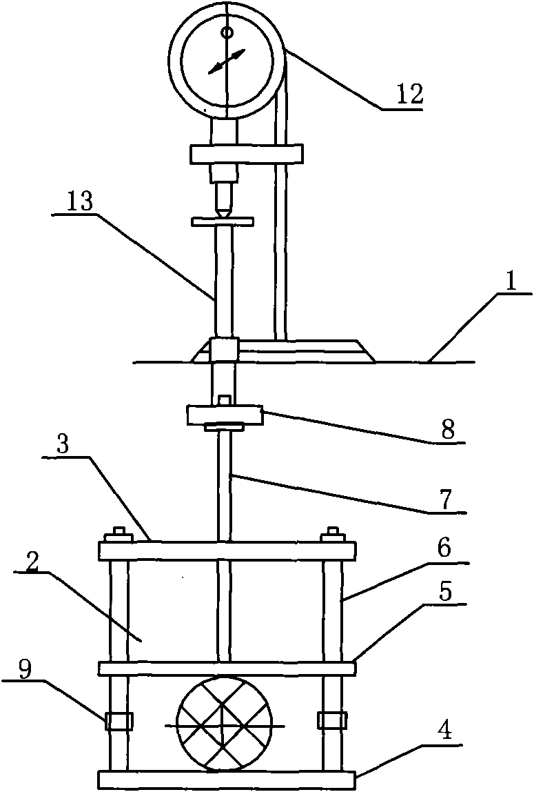
[0047] Such as image 3 As shown, a thermal deformation detector includes an oven (1), and a sample rack (2) is arranged inside the oven (1). The sample rack includes an upper plate (3), a lower plate (4) and a horizontally arranged upper plate. The load pressing plate (5) between the plate (3) and the lower plate (4), and the guide column (6) for fixedly connecting the upper plate (3) and the lower plate (4) are arranged around the sample holder (2), the guide The column (6) passes through the load pressing plate (5) vertically, and the load pressing plate (5) can move up and down along the guide column (6). 7) Pass through the upper plate (3) and connect with the load-bearing plate (8) provided outside the sample holder, and a displacement measuring device (9) is provided on the guide column (6) between the load platen (5) and the lower plate (4). ), the oven (1) is provided with a dial indicator (12), and the dial indicator (12) is connected with the center of the load-bea...


PUM


Abstract

The invention discloses a heat deformation detection instrument, which comprises a baking oven, wherein a test specimen frame is arranged inside the baking oven. The invention is characterized in that the test specimen frame comprises an upper frame, a lower frame and a load pressure plate arranged between the upper plate and the lower plate, the circumference of the test specimen frame is provided with a guide post used for fixedly connecting the upper plate and the lower plate, the guide post vertically passes through the load pressure plate, the center of the upper surface of the load pressure plate is vertically provided with a load pressure rod, the load pressure rod passes through the upper plate to be connected with a load bearing disc arranged outside the test specimen frame, and a displacement measuring device is arranged on the guide post arranged between the load pressure plate and the lower plate. The invention has the advantages that the measuring deviation caused by deformation inclination of the test specimen, the self weight of a dial indicator and the measured deviaton of the nonuniform heating of the test specimen inside the baking oven can be avoided, and the accuracy of the measuring results can be ensured.

Description

technical field [0001] The invention relates to a measuring instrument, in particular to a thermal deformation detector. Background technique [0002] The thermal deformation detector is a measuring instrument used to measure the thermal deformation of polymer materials or polymers. Thermal deformation detection is caused by applying a certain load to polymer materials or polymers and keeping them at a specified temperature for a certain period of time. The amount of deformation is a measurement method to measure the heat resistance of polymers or polymer materials. [0003] The existing thermal deformation detector includes an oven, a dial gauge outside the oven, and a sample holder inside the oven. When measuring, the sample is placed in the sample holder and the dial gauge is used to measure the deformation of the sample. , has the advantages of simple structure and convenient use. However, since the dial indicator is located on one side of the sample holder, the sample ...

Claims


Application Information

Patent Timeline
Patent Type & Authority Applications(China)
IPC IPC(8): G01B5/30
Inventor 邵丽萍陈章娥
Owner 宁波市产品质量监督检验研究院
Why Eureka
Try Eureka