Impact load location method based on multiple signal classification algorithm

A technology of multiple signal classification and positioning methods, applied in the field of structural impact load position identification, can solve problems such as instability, impact monitoring difficulty, and large training workload, and achieve the effect of ensuring safe operation, high positioning accuracy, and strong real-time performance.

Active Publication Date: 2010-10-20
NANJING UNIV OF AERONAUTICS & ASTRONAUTICS
View PDF0 Cites 36 Cited by
  • Summary
  • Abstract
  • Description
  • Claims
  • Application Information

AI Technical Summary

Benefits of technology

The technical effect of this new technology described by BENFAR is that it provides an easy way for engineers to monitor their safety during construction without having to stop working or take other measures like rebuilding them after they have been completed. This makes sure things are safe from damage caused due to unexpected events happening around us.

Problems solved by technology

This patented technical problem addressed in this patents relates to improving the accuracy and reliability of detecting impact events within a wide range of sizes (up to 100 mm) without requiring expensive instrumentations like nondestrusion inspections or destructive evaluation. Current solutions involve manually identifying impact sources through visual examinations and static analysis technologies, which may result in overlooking critical areas where significant failures could happen before reaching end users' confidence levels. Additionally, existing solutions rely heavily upon simulations involving full body simulation, which requires extensive computational resources and cannot provide accurate data feedback when needed.

Method used


Image

  • Impact load location method based on multiple signal classification algorithm
  • Impact load location method based on multiple signal classification algorithm
  • Impact load location method based on multiple signal classification algorithm

Examples


Embodiment

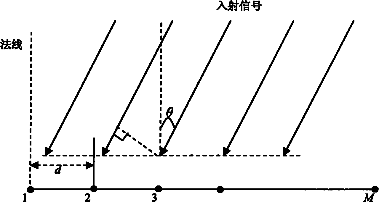
[0083] The test piece is a T-30 carbon fiber composite laminate with a size of 610×610×2mm, and the four sides are fastened to the fixture by screws. The material of the carbon fiber layup is T300 / QY8911, and the layup sequence is [45 / 0 / -45 / 90 / 0 / 45 / 0 / -45 / 0] S . A uniform linear array composed of 7 identical piezoelectric sheets is adopted, and the distance between the centers of two adjacent piezoelectric sheets is 1.1 cm. The array elements are numbered from 0 to 6 from left to right, with the center of the 0 piezoelectric sheet as the coordinate origin, the axis of the piezoelectric array as the real axis, and the direction perpendicular to the array as the normal direction. Such as image 3 shown. The sensing element is a PZT-5 piezoelectric film with a diameter of 8mm and a thickness of 0.48mm. The impact tool is a spring mechanical impact rod with two levels of impact energy. The top of the impact head is hemispherical with a diameter of 10mm, such as image 3 shown....


PUM


Abstract

The invention discloses a structural impact load location method based on multiple signal classification algorithm, comprising the following steps: step 1: collecting impact response signals; step 2: conducting estimation of direction-of-arrival of impact source by utilizing the multiple signal classification algorithm; and step 3: conducting estimation of distance of the impact source according to the propogation characteristic of Lamb wave. The method in the invention is convenient and reliable, can perform real-time and online monitoring to the impact; and has high-precision impact location and strong instantaneity.

Description


Claims


Application Information

Patent Timeline
Owner NANJING UNIV OF AERONAUTICS & ASTRONAUTICS
Why Eureka
Try Eureka