Image processing apparatus and image processing method
一种图像处理装置、图像数据的技术,应用在图像通信、电气元件等方向
- Summary
- Abstract
- Description
- Claims
- Application Information
AI Technical Summary
Problems solved by technology
Method used
Image
Examples
no. 1 example
[0042] Example configuration of an image processing device according to an embodiment of the present invention
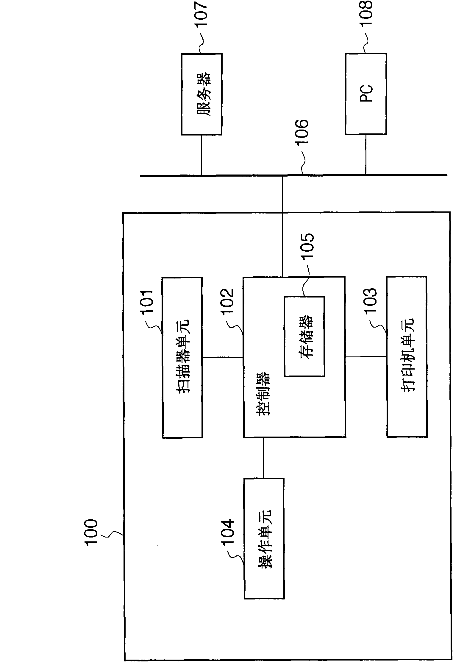
[0043] figure 1 is a schematic block diagram of the image processing apparatus 100 , and is a block diagram of, for example, a digital multifunction peripheral having general functions such as copying, printing, and facsimile.
[0044]The image processing apparatus 100 according to the present embodiment includes a scanner unit 101 that reads a document, and a controller 102 that performs image processing on image data read by the scanner unit 101 and stores the image data in a memory 105 . The image processing apparatus 100 also includes an operation unit 104 that sets various printing conditions for image data read by the scanner unit 101 . The image processing apparatus also includes a printer unit 103 that visualizes image data read from the memory 105 to form an image on recording paper according to printing conditions set by the operation unit 104, and the l...
example 2
[0106] Figure 11A Image data composed of a pixel 2401 and a pixel 2402 are illustrated, the pixel value of the pixel 2401 for K is "0", and the pixel value of the pixel 2402 for K is "120". In the attribute data, pixel 2401 corresponds to Figure 10B Pixel 2101 in , pixel 2402 corresponds to Figure 10B Pixel 2102 in . The digital halftone processing performed by the halftone processing unit 304 will Figure 11A Pixel 2401 in converts to eg Figure 11B A pixel 2501 with a pixel value of "0" for K is shown. On the other hand, the pixel 2402 is converted into a pixel 2502 whose pixel value for K is "0" and a pixel 2503 whose pixel value for K is "15".
[0107] Figure 11C exemplified as a pair Figure 11A , Figure 10B as well as Figure 11B Halftone image data obtained as a result of performing smoothing processing according to the present embodiment. It can also be seen that in this case, light colored pixels 2601, 2602, and 2603 are added to the boundary between pi...
example 3
[0109] Figure 12A Image data composed of a pixel 2701 and a pixel 2702 are illustrated, the pixel value of the pixel 2701 for K is "120", and the pixel value of the pixel 2702 for K is also "120". In the attribute data, pixel 2701 corresponds to Figure 10B Pixel 2101 in , pixel 2702 corresponds to Figure 10B Pixel 2102 in . The digital halftone processing performed by the halftone processing unit 304 will Figure 12A Pixel 2701 in converts to eg Figure 12B A pixel 2801 with a pixel value for K of "15" and a pixel 2802 with a pixel value for K of "0" are shown. Similarly, the Figure 12A Pixel 2702 in converts to eg Figure 12B A pixel 2803 with a pixel value for K of "0" and a pixel 2804 with a pixel value for K of "15" are shown.
[0110] in the right Figure 12A , Figure 10B as well as Figure 12B In the case where the smoothing process according to this embodiment is performed, since there is no pixel value boundary between the pixel 2701 and the pixel 2702, th...
PUM
 Abstract
Description
Claims
Application Information
 - R&D
- Intellectual Property
- Life Sciences
- Materials
- Tech Scout
- Unparalleled Data Quality
- Higher Quality Content
- 60% Fewer Hallucinations
Browse by: Latest US Patents, China's latest patents, Technical Efficacy Thesaurus, Application Domain, Technology Topic, Popular Technical Reports.
© 2025 PatSnap. All rights reserved.Legal|Privacy policy|Modern Slavery Act Transparency Statement|Sitemap|About US| Contact US: help@patsnap.com


