Method and device for converting video image format

A format conversion and video image technology, applied in the field of video image format conversion methods and devices, can solve the problems of slow processing speed, complicated steps of table look-up method, etc., and achieve the effect of improving processing efficiency

Inactive Publication Date: 2010-10-20
IDEAPOOL CULTURE & TECH CO LTD
7 Cites 17 Cited by

AI-Extracted Technical Summary

Problems solved by technology

Although the conversion speed can be improved to a certain extent, there are also technical deficiencies and defects. For example, the complete table lookup method requires a large enough storage device, and some table lookup methods have cumbersome steps and slow processing speed.
[0004] With the development of digitizatio...

Method used

[0023] Step 304, each data processing unit 1043 converts YUV420 data into RGB32 data and stores in parallel. Due to the particularity of video data, each pixel is 32-bit data, and we can use large-digit registers to process data of multiple pixels in parallel, further improving the conversion speed.
[0024] Step 305, scheduling unit 103 waits for all data processing units 1043 to complete all data processing. Utilizing the management function of the scheduling unit 103 ensures the synchronization of th...

Abstract

The invention relates to a method and a device for converting a video image format. The method comprises the following steps of: generating a data processing unit in each central processing unit according to the number of central processing units; acquiring real-time YUV data from the outside by using a data acquisition unit and storing the YUV real-time data in a main storage unit; averagely splitting the YUV real-time data in the main storage unit into a corresponding number of equally-divided parts according to the number of generated data processing units; averagely distributing the plurality equally-divided parts of split data to each data processing unit and monitoring the running state of the data processing unit; converting split data in parallel into RGB data by using each data processing unit; and storing the converted RGB data in the main storage unit. Due to the adoption of the method and the device, the processing capability of the central processing unit can be utilized to the maximum extent and video image format converting efficiency is further improved.

Application Domain

Technology Topic

Image

  • Method and device for converting video image format
  • Method and device for converting video image format
  • Method and device for converting video image format

Examples

  • Experimental program(1)

Example Embodiment

[0018] In the field of digital broadcasting and television, two formats, YUV and RGB, are often encountered. The YUV format contains a variety of specific color expressions, such as YUV422, YUV420, YUV444, etc. The RGB format also contains a variety of specific color expressions, such as RGB565 , RGB24, RGB32, etc. The embodiments of the present invention mainly take the conversion of YUV420 and RGB32 formats as an example to illustrate the present invention.
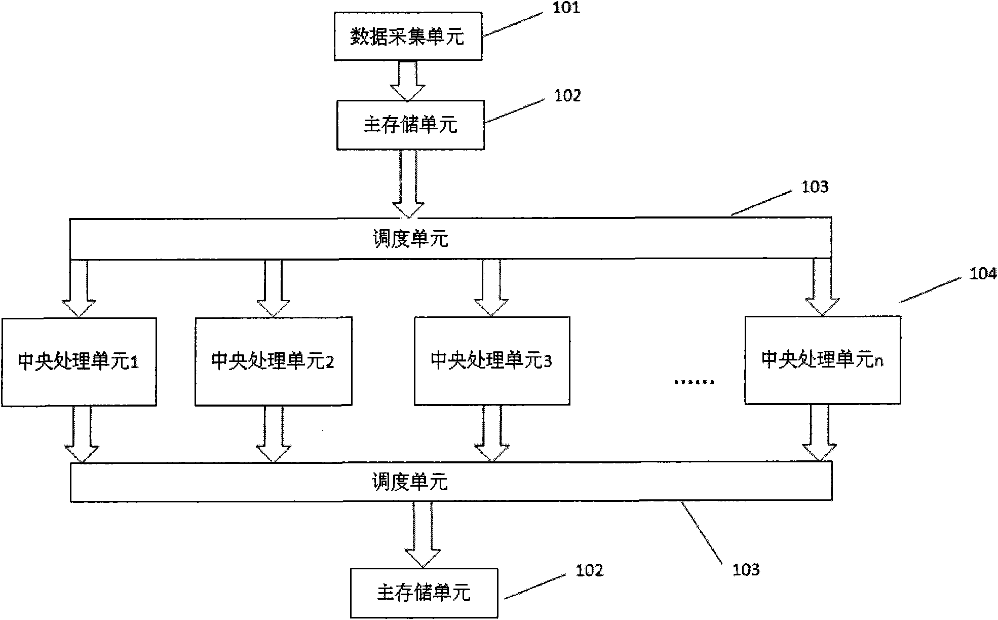
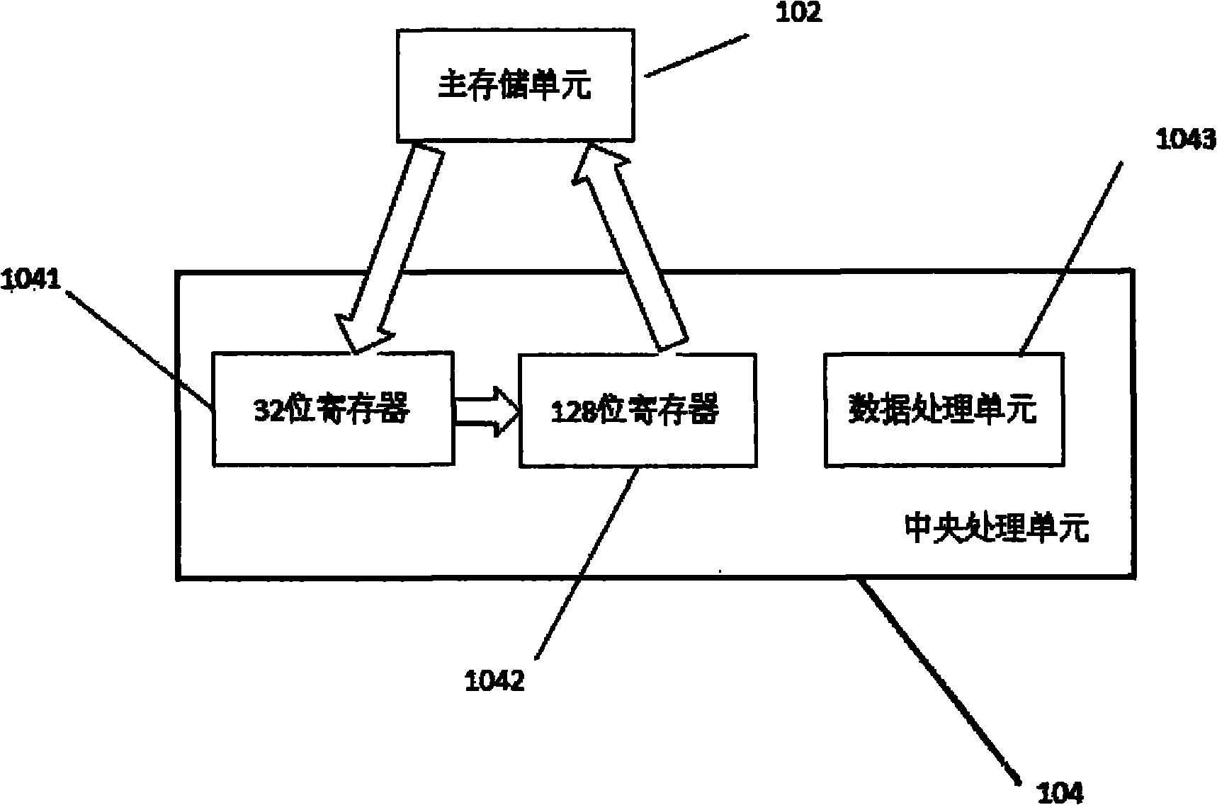
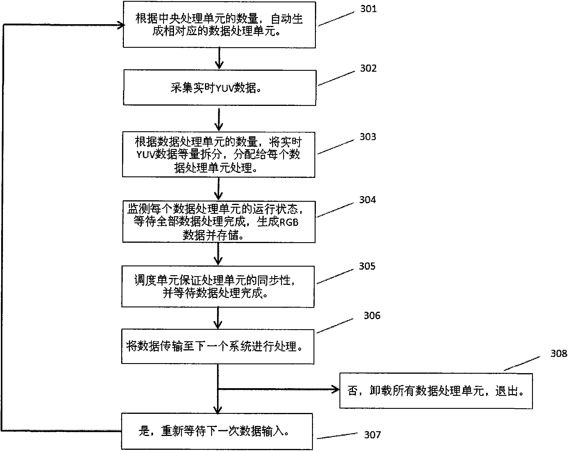
[0019] Attached below figure 1 , attached figure 2 and attached image 3 An embodiment of the present invention is described (taking the conversion from YUV420 format to RGB32 format as an example).
[0020] In step 301, the system is initialized, that is, the scheduling unit 103 generates a data processing unit 1043 in each central processing unit 104 according to the number of the central processing units 104, and the scheduling unit 103 automatically monitors the running status of each data processing unit 1043. .
[0021] Step 302 , collect real-time YUV420 data through the data collection unit 101 , and store the collected data in the main storage unit 102 . The data collection unit 101 collects data through a video collection card. Here, it is taken as an example that the data collection unit 101 is provided with one video collection card, and one frame of data is collected at a time.
[0022] Step 303, the scheduling unit 103 divides the real-time YUV data into a plurality of equal parts of the corresponding number on average according to the number of the generated data processing units 1043, and transmits each part of the data to different data processing units 1043 for parallel processing, while monitoring. The operating status of each data processing unit 1043, and the processing task status of each data processing unit 1043 is set to the busy status. The principle of data splitting is to divide the data equally based on the load balancing of all data processing units 1043 . Since each data processing unit 1043 is in a different central processing unit 104, the processing tasks of each data processing unit 1043 are parallel, and the resources of the central processing unit 104 can be fully utilized to maximize the speed of data conversion.
[0023] Step 304, each data processing unit 1043 converts the YUV420 data into RGB32 data in parallel and stores it. Due to the particularity of video data, each pixel is 32-bit data, we can use large-bit registers to process the data of multiple pixels in parallel, which further improves the conversion speed.
[0024] Step 305, the scheduling unit 103 waits for all the data processing units 1043 to complete the processing of all the data. The management function of the scheduling unit 103 is used to ensure the synchronization of processing, and to ensure that the output data is the data of the same frame without errors.
[0025] In step 306, the scheduling unit 103 transmits the data processed by the data processing unit 1043 to the image and text processing system or other systems for processing. The converted data is 32-bit RGB data.
[0026] Step 307 , waiting for the next YUV data collection by the video collection unit 101 .
[0027] Step 308, if there is no data processing task, uninstall all data processing units 1043 and exit.
[0028] Further, as attached figure 2 As shown, the central processing unit includes a data processing unit, a 32-bit register and a 128-bit register. The data processing unit is used for processing the data allocated by the scheduling unit.
[0029] attached Figure 4 is attached figure 1 A detailed description of the data processing performed by the data processing unit 1043 in .
[0030] The basic conversion formula between YUV and RGB is:
[0031] R=Y+1.4075*(V-128)
[0032] G=Y-0.3455*(U-128)-0.7169*(V-128)
[0033] B=Y+1.779*(U-128)
[0034] On the basis of this formula, the appendix Figure 4 The data processing flow shown includes the following steps:
[0035] Step 401: Perform integer processing on the factors in the above conversion formula, that is, amplify all the factors in the formula by 1024 times, generate 5 integer factors fY, fRv, fGu, fGv, fBu, and then take them into integers, and use the processed integer factors The equal amount is divided into four parts and stored in the 128-bit register 1041.
[0036] Step 402 , the data processing unit 1043 moves the YUV420 data from the main storage unit 102 to the 32-bit register 1041 , processes and splits the YUV420 data in the 32-bit register 1401 , and moves it to the 128-bit register 1042 .
[0037] In step 403, the data processing unit 1403 simultaneously performs the conversion task on the divided four pixels through the processed integer factor calculation formula, so as to improve the conversion efficiency.
[0038] Step 404, it is judged whether all the data is completed, if not, the process of steps 402 to 403 is continued. If completed, the setting of the flag is completed, and when the scheduling unit 103 checks the flag, the data processing unit 1043 is set to an idle state. If not completed, it will always remain busy.
[0039] Step 405 , shift the converted RGB32 data from the 128-bit register 1042 to the main storage unit 102 . Complete the conversion processing of multiple pixels at a time.
[0040] attached Figure 5 is attached Figure 4 A detailed description of the multi-data parallel processing in steps 401 to 403.
[0041] as attached Figure 5 The processing flow shown, the specific implementation steps are as follows:
[0042] Step 501 , the data processing unit 1043 moves the YUV420 data from the main storage unit 102 to the 32-bit register 1041 .
[0043] Suppose the width of the image is Width and the height is Height. Each pixel consists of a Y value, a total of Width*Height data.
[0044] Every four pixels share a U value, a total of Width*Height/4 U values.
[0045] Every four pixels share a V value, a total of Width*Height/4 V values.
[0046] The data storage format is:
[0047] Y Y Y Y Y Y Y Y
[0048] U U U U
[0049] V V V V
[0050] Y Y Y Y Y Y Y Y
[0051] Step 502 , the data processing unit 1043 splits the YUV420 from the 32-bit register 1041 into the 128-bit register 1042 .
[0052] Move into 128-bit register 1042: 00000000 00000000 00000000 yyyyyyyy
[0053] Split: 000000yy 000000yy 000000yy 000000yy
[0054] Do the same for the U and V data:
[0055] 00000000 00000000 00000000 uuuuuuuu
[0056] 000000uu 000000uu 000000uu 000000uu
[0057] 00000000 00000000 00000000 vvvvvvvv
[0058] 000000vv 000000vv 000000vv 000000vv
[0059] Step 503, the data processing unit 1043 performs integer transformation on the data, and the data transformation is as follows:
[0060] Integer factor: fY----Y magnification factor
[0061] Y=Y*fY
[0062] U=U-128
[0063] V=V-128
[0064] Step 504: Calculate the R, G, B values, and the Alpha bit is automatically filled with 255, indicating that it is completely opaque.
[0065] There are four arithmetic integer factors:
[0066] fRv----the magnification factor of V in the red component
[0067] fGu----The magnification factor of U in the green component
[0068] fGv----The magnification factor of V in the green component
[0069] fBu----The magnification factor of the blue component weight U
[0070] Then the calculation formula becomes the integer factor calculation formula as follows:
[0071] R=Y+fRv*V
[0072] G=Y+fGu*U+fGv*V
[0073] B=Y+fBu*U
[0074] Step 505 , combine each calculated component into a pattern of ffrrggbb ffrrggbb ffrrggbb ffrrggbb to generate RGB32 format data, and the data processing unit 1043 shifts the RGB32 data from the 128-bit register 1042 to the main storage unit 102 .
[0075] Finally, it should be noted that the method of the present invention includes but is not limited to the specific examples in the specific implementation manner. If the hardware conditions permit, for example, the data acquisition unit adopts a multi-channel video acquisition card, it can collect multiple frames of data into the Therefore, other specific embodiments obtained by making various changes and modifications without departing from the technical content of the present invention also belong to the protection scope of the present invention.
[0076] The present invention mainly generates a corresponding number of data processing units according to the number of central processing units, thereby increasing the speed of data processing.

PUM

no PUM

Description & Claims & Application Information

We can also present the details of the Description, Claims and Application information to help users get a comprehensive understanding of the technical details of the patent, such as background art, summary of invention, brief description of drawings, description of embodiments, and other original content. On the other hand, users can also determine the specific scope of protection of the technology through the list of claims; as well as understand the changes in the life cycle of the technology with the presentation of the patent timeline. Login to view more.

Similar technology patents

Segmented crankshaft machining process

ActiveCN103009021AImprove yield and process qualityImprove processing efficiencyProcessing accuracyMachining process
Owner:SICHUAN MIANZHU XINKUN MACHINERY MAKING

Classification and recommendation of technical efficacy words

Why Eureka
Try Eureka