Ink jet print head with automated cleaning at the start of printing

A print head, print head technology, applied in the field of inkjet print heads that are automatically cleaned at the beginning of printing, can solve the problems of high cost of cleaning measures, long operating time, etc., achieve excellent jet start reliability, prevent pollution, and high efficiency Effect

Inactive Publication Date: 2010-10-20
MARKEM IMAJE HLDG
View PDF1 Cites 8 Cited by
  • Summary
  • Abstract
  • Description
  • Claims
  • Application Information

AI Technical Summary

Problems solved by technology

[0020] - the cleaning measure is costly and requires a long operating time

Method used


Image

  • Ink jet print head with automated cleaning at the start of printing
  • Ink jet print head with automated cleaning at the start of printing
  • Ink jet print head with automated cleaning at the start of printing

Examples


Embodiment Construction

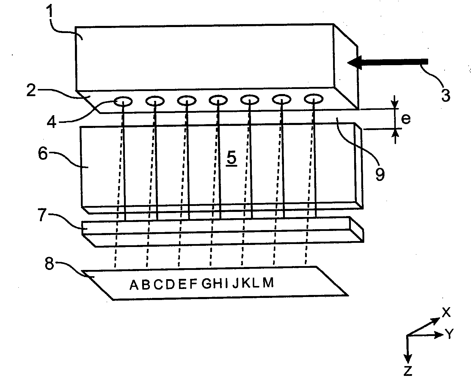
[0049] The print head T according to the invention comprises a droplet generator 1 equipped with a nozzle plate 2 . During the printing phase, the ink 3 pressurized in the generator 1 flows out through the nozzles 4 to form a jet curtain. Downstream of the nozzle plate 2 in the ink flow direction (along the Z-axis), a sorting block 5 including a functional electrode portion 6 is positioned. The role of this electrode part 6 is to be placed on the different jet trajectory parts, most of the jets are collected by the recirculation compartment 7, while the other jets are directed towards the medium to be printed 8 ( figure 1 ).

[0050] The terms "lower" and "upper" are to be understood as orienting the print head downwards (jet flow in z direction), in other words having the aforementioned generator 1 partly directly above the electrode block 5 according to the invention.

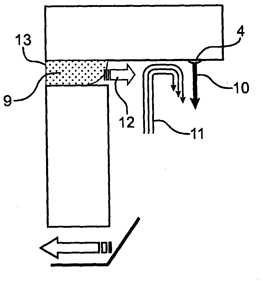
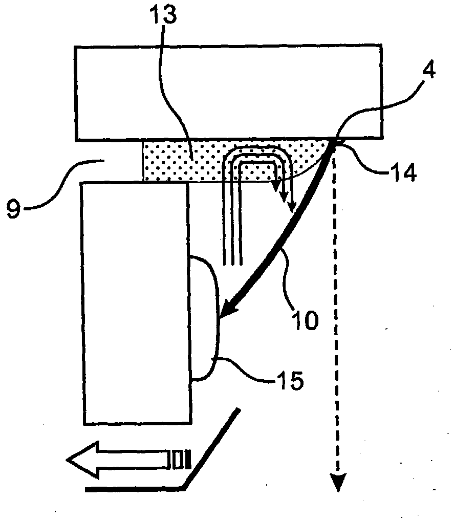
[0051] Between the nozzle plate 2 and the sorting block 5, a space 9 is constructed, the thickness of wh...


PUM


Abstract

Liquid jet print head (3) comprising: a generator (1) of drops of liquid, the lower part of which comprises a plate (2) equipped with at least one nozzle (4) for ejecting the liquid, a sorting block (5) laid out below the nozzle plate (2) and offset in relation to the axis (Z) of the nozzle; wherein the block and the generator are fixed in relation to each other by delimiting a first space (9) and by forming an angle alpha in a vertical plane (YZ), means (50, 51) to suck up any stagnant liquid (13) in the first space and / or in the angle before the ejection of liquid via the nozzle at the start up of printing.

Description

technical field [0001] The present invention relates to the field of printing by ejection or dripping of liquids such as ink. [0002] The invention relates to making the start-up of a liquid jet printer reliable during the phase of forming said liquid jet. [0003] The present invention more particularly relates to cleaning any lingering liquid near the orifice through which liquid, such as ink, is ejected, before printing begins. [0004] An advantageous field of application is inkjet printing. Background technique [0005] The basic principle of an inkjet printer is to force a liquid (usually ink) through calibrated orifices. [0006] Individual or common actuators for the nozzles pressurize the ink upstream of the nozzles. The ink is ejected at a speed of several meters to tens of meters per second depending on the printing technology. Depending on whether "drop-on-demand" or "continuous-jet" printing techniques are involved, the passage of the ink to the free surfac...

Claims


Application Information

Patent Timeline
Patent Type & Authority Applications(China)
IPC IPC(8): B41J2/17B41J2/20
CPCB41J2/08B41J2/20B41J2/1714B41J2/185
Inventor 埃尔韦·格莱戈瓦
Owner MARKEM IMAJE HLDG
Why Eureka
Try Eureka