Method for controlling a stationary gas motor

A gas engine, stationary technology, applied in the direction of combustion engine, internal combustion piston engine, engine control, etc.

Inactive Publication Date: 2010-10-20
MOTOREN UND TURBINEN UNION MUNCHEN GMBH
View PDF2 Cites 7 Cited by
  • Summary
  • Abstract
  • Description
  • Claims
  • Application Information

AI Technical Summary

Problems solved by technology

This can lead to an overshoot of the adjustment variable in some cases

Method used


Image

  • Method for controlling a stationary gas motor
  • Method for controlling a stationary gas motor
  • Method for controlling a stationary gas motor

Examples


Embodiment Construction

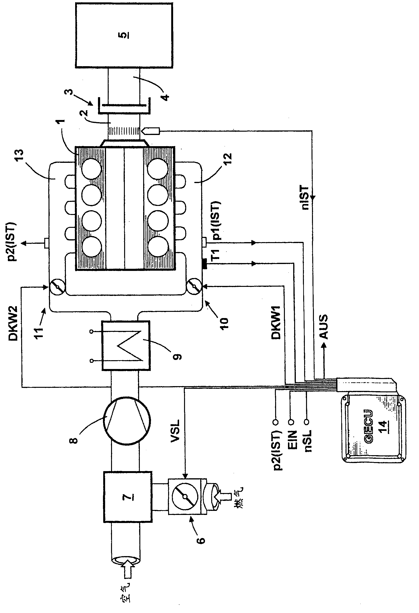
[0015] figure 1 A general view of a stationary gas engine 1 arranged in a V shape is shown. Gas engine 1 drives generator 5 via shaft 2 , clutch 3 and shaft 4 . Electrical energy is generated by the generator 5 and fed into the grid. The gas engine 1 is associated with the following mechanical components: a gas throttle valve 6 for determining the volume flow of the delivered gas (e.g. exhaust gas); a mixer 7 for combining air and gas; as an exhaust gas turbocharger compressor 8 ; cooler 9 ; a first mixture throttle valve 10 on the A side of the gas engine 1 and a second mixture throttle valve 11 on the B side of the gas engine 1 .

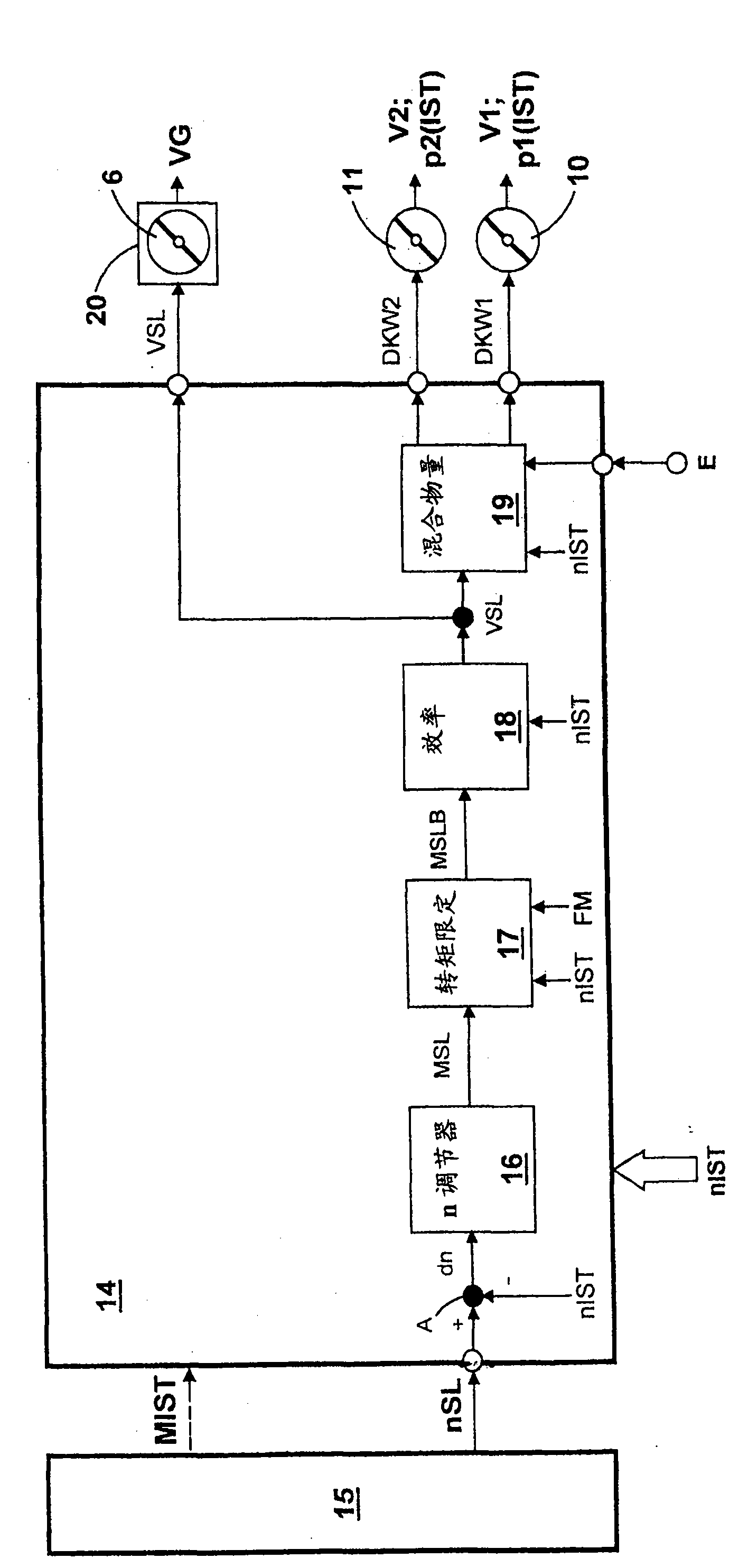
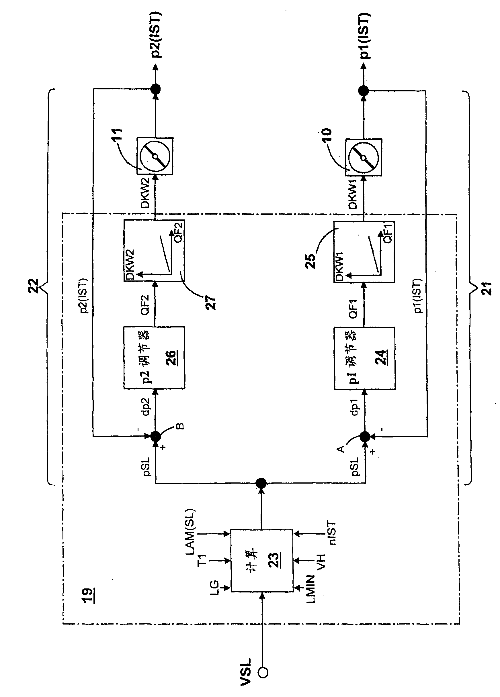
[0016] The mode of operation of gas engine 1 is determined by electronic engine controller 14 (GECU). The electronic engine controller 14 contains the usual components of a microcomputer system, such as a microprocessor, I / O modules, buffers and memory modules (EEPROM, RAM). Operating data relating to the operation of the gas engine 1 are impl...


PUM


Abstract

The invention proposes a method for controlling a stationary gas motor (1), wherein a rotational speed control deviation is calculated from a target rotational speed (nSL) and a current rotational speed (nIST), a target torque is determined from the rotational speed control deviation as the controlled variable, wherein a mixture throttle angle (DKW1, DKW2) is determined for the determination of amixture volume flow and of a current mixture pressure (p1 (IST), p2(IST)) in a receiver pipe (12, 13) upstream of the intake valves of the gas motor (1) as a function of the target volume flow, and wherein a gas throttle angle is determined for determining a gas volume flow as the gas content in a gas / air mixture, also as a function of the target volume flow.

Description

technical field [0001] The invention relates to a method for adjusting fixed Method for a gas engine (Gasmotor), wherein the rotational speed adjustment deviation is calculated from the theoretical rotational speed and the actual rotational speed, and the rotational speed adjustment deviation is determined as the adjustment variable by the rotational speed regulator The theoretical torque and the theoretical volume flow is determined with the aid of the theoretical torque. Furthermore, the method consists in determining the mixture throttle valve opening angle (Gemisch-Drosselklappenwinkel) as a function of the set volume flow for determining the mixture volume flow in the receiver pipe (Receiverrohr) upstream of the intake valve (Einlassventil) of the gas engine and The actual mixture pressure, and also depending on the target volume flow, is used to determine the gas throttle valve opening angle for determining the gas volume flow as a gas fraction in the gas-air mixture....

Claims


Application Information

Patent Timeline
Patent Type & Authority Applications(China)
IPC IPC(8): F02D41/00F02D41/14F02D41/18F02D19/02F02D11/10
CPCF02D29/06Y02T10/32F02D41/0027F02D2200/0404F02D19/023F02D2200/0406F02D2200/0408F02D11/10F02D41/1497F02D41/18F02B29/0406Y02T10/30
Inventor J·巴尔多夫L·克拉泽-杰尼韦因P·斯姆达
Owner MOTOREN UND TURBINEN UNION MUNCHEN GMBH
Why Eureka
Try Eureka