Preheater for heating molten alloy

A liquid alloy and preheater technology, applied in water heaters, fluid heaters, and the shape of heating elements, etc., can solve the problems of shortening the service life of heating wires, increasing the temperature of heating wires, and lengthening material pipelines, etc., so as to save materials and space, reduce the overall size, the effect of compact arrangement

Pending Publication Date: 2018-08-24
CHINA NUCLEAR POWER TECH RES INST CO LTD +2
View PDF7 Cites 2 Cited by
  • Summary
  • Abstract
  • Description
  • Claims
  • Application Information

AI Technical Summary

Problems solved by technology

[0007] The heating part of some preheaters is the electric heating layer covered by the material pipe. The heat transfer of the electric heating layer also needs to conduct heat through the pipe, and the heat transfer efficiency is low. In order to obtain a large temperature rise, the heat exchange area must be increased, which will cause As a result, the material pipeline becomes longer and the resistance of the circuit increases; in addition, the external heating of the tube, the thermal resistance is large, and the temperature of the heating wire itself increases, which increases the difficulty of manufacturing the heating wire and shortens the service life of the heating wire; in order to save space, the material pipeline is curved, although Saves space, but further increases loop resistance
[0008] In some preheaters, the sealing method between the end cover and the heating rod is non-detachable. Once the heating rod is damaged, it is difficult to replace the heating rod; the preheater of the liquid metal sodium experimental circuit is a rectangular cross-section pressure vessel, resistant to The pressure performance is not as good as that of a cylindrical pressure vessel, and when the same amount of material is used, the volume is smaller than that of a cylindrical pressure vessel; this type is a preheater for liquid metal sodium, and if it is used for liquid lead-bismuth alloy, the actual application effect unknown

Method used


Image

  • Preheater for heating molten alloy
  • Preheater for heating molten alloy
  • Preheater for heating molten alloy

Examples


Embodiment Construction

[0034] In order to have a clearer understanding of the technical features, purposes and effects of the present invention, the specific implementation manners of the present invention will now be described in detail with reference to the accompanying drawings.

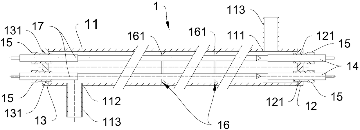
[0035] like figure 1 As shown, the preheater for heating liquid alloy in a preferred embodiment of the present invention includes a preheating assembly 1, and there may be one preheating assembly 1, or there may be multiple preheating assemblies.

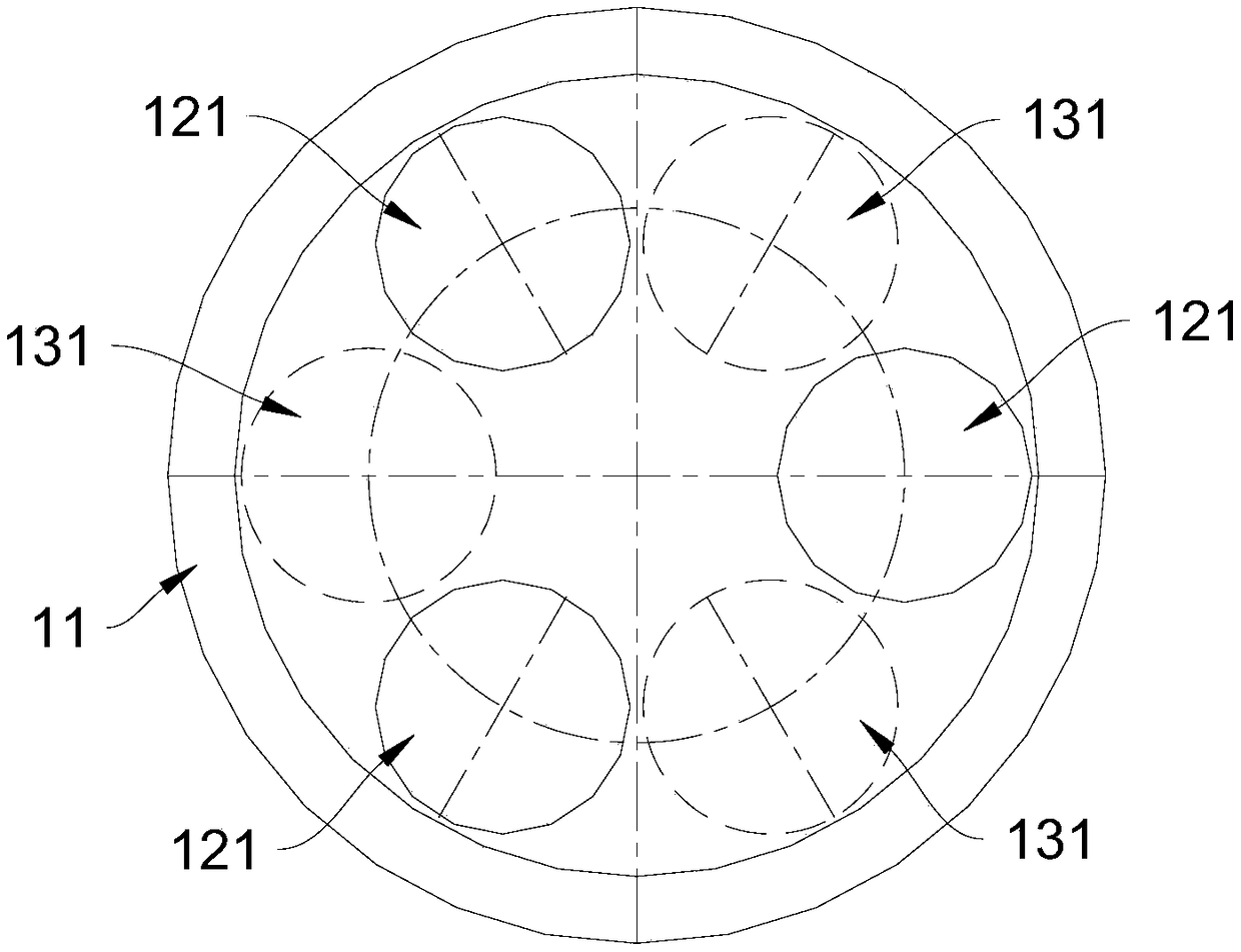
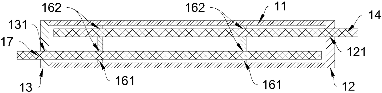
[0036] In some embodiments, the preheating assembly 1 includes a cylinder body 11 , a first end cover 12 , a second end cover 13 , three first heating rods 14 , and three second heating rods 17 .

[0037] The side wall of the cylinder body 11 is provided with a first interface 111 and a second interface 112. The first interface 111 and the second interface 112 are respectively close to the two ends of the cylinder body 11, allowing the liquid alloy to pass through the first i...


PUM


Abstract

The invention relates to a preheater for heating molten alloy. The preheater comprises a preheating assembly, and the preheating assembly comprises a barrel, a first end cover, a second end cover, first heating rods and second heating rods. The side wall of the barrel is provided with a first joint and a second joint which are close to the end parts of both ends of the barrel separately. The firstend cover and the second end cover are arranged at the two ends of the barrel in a covering mode separately. The first end cover is provided with first insertion-connection holes, the second end cover is provided with second insertion-connection holes, and the first insertion-connection holes and the second insertion-connection holes are arranged in a staggered mode. The first heating rods penetrate into the barrel from one end via the first insertion-connection holes, and the second heating rods penetrate into the barrel from the other end via the second insertion-connection holes. Since thefirst insertion-connection holes and the second insertion-connection holes in the two ends are staggered, the intervals between the heating rods at the same end are large, and thus quick connectors on the heating rods at the same end can be installed advantageously; and the intervals between the heating rods can be decreased, so that the heating rods are distributed more closely, the size of thebarrel is reduced, and materials and space are saved.

Description

technical field [0001] The invention relates to the technical field of heating equipment, in particular to a preheater for heating liquid alloys. Background technique [0002] At present, the preheater used for lead-bismuth alloy is mainly heated by electric heating elements to make the temperature of lead-bismuth alloy meet the process requirements. Conventional electric heating elements include electrodes (clamped at both ends of the preheater and directly energized), electric heating wires, electric heating rods and silicon carbide rods, etc. [0003] Electrode direct heating is not suitable for lead-bismuth alloy, because lead-bismuth alloy has good conductivity, this way will make the whole loop electrified, and its resistance characteristics greatly increase the burden of this heating method; in addition, considering the oxygen control Factors such as factors will cause an oxide layer to appear on the wall of the structural material, which increases the uncertainty of...

Claims


Application Information

Patent Timeline
Patent Type & Authority Applications(China)
IPC IPC(8): F24H1/10F24H9/18H05B3/44
CPCH05B3/44F24H1/103F24H9/1818
Inventor 梁振辉周炜翔陈树毅梁峻铭荣刚刘欣
Owner CHINA NUCLEAR POWER TECH RES INST CO LTD
Why Eureka
Try Eureka